

Help text
Please read the whole document without assumptions from previous rules documents.
When you see green italic text, this is intended to help clarify a regulation or diagram.
When you see the PP+ symbol in the margin, this means a rule carries a Proportional Penalty. Find out more about Proportional Penalties and the classification of rules in T2.5.
Article T1 Definitions
T1.1 STEM Racing™ India car
This is also referred to as ‘the car’. Designed and manufactured according to these regulations for the purpose of participating in races on the STEM Racing™ India track at the National Finals event, powered only by a single 8 grams power unit cartridge. STEM Racing™ India cars are designed to travel the 20-metre race and withstand the physical deceleration required after crossing the finishing line.
A STEM Racing™ India car assembly must only consist of the following components:
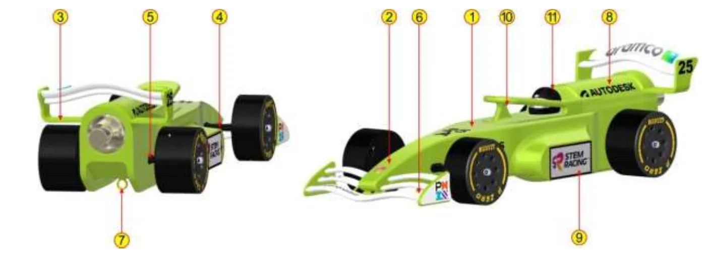
Adhesives with no dimensional impact are permissible for joining components.
Example parts:
- A body encompassing a virtual cargo and a power unit cartridge chamber machined from a single piece of STEM Racing™ Model Block Material
- Nose cone assembly (Optionally Replaceable)
- Front wing support structure
- Front wing(s)
- End plates
- Rear Wing Assembly
- Rear wing support structure
- Rear wing(s)
- End plates
- Front wheel support system(s)
- Front wheel(s) rotating.
- Wheel support structure non rotating
- Rear wheel support system(s)
- Rear wheel(s) rotating.
- Wheel support structure non rotating
- Front tether line guide
- Rear tether line guide
- Surface finishing and decals
- STEM Racing™ India Logo Decal (2)
- Halo
- Drivers Helmet
- Legal Ballast
- Refer to T1.22 and T4 for more information
T1.2 Fully assembled car
A STEM Racing™ India car, without a power unit cartridge inserted, presented ready for racing, resting on all four wheels on the track surface, free of any external force other than gravity.
T1.3 Body
The body is a single uninterrupted piece of STEM Racing™ Model Block material existing rear of reference plane A and encompassing both the virtual cargo and power unit cartridge chamber. For dimensional purposes the body also includes any attached decals and surface finishes. Any STEM Racing™ Model Block forward of reference plane A is not defined as body.
T1.4 Power unit cartridge chamber
The power unit cartridge chamber is a cylindrical clear space bounded around its inner circumference and forward end by car body only. This is where the power unit cartridge is placed for racing.
T1.5 Wing
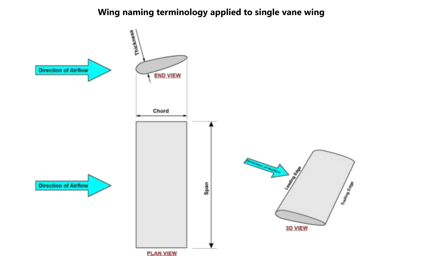
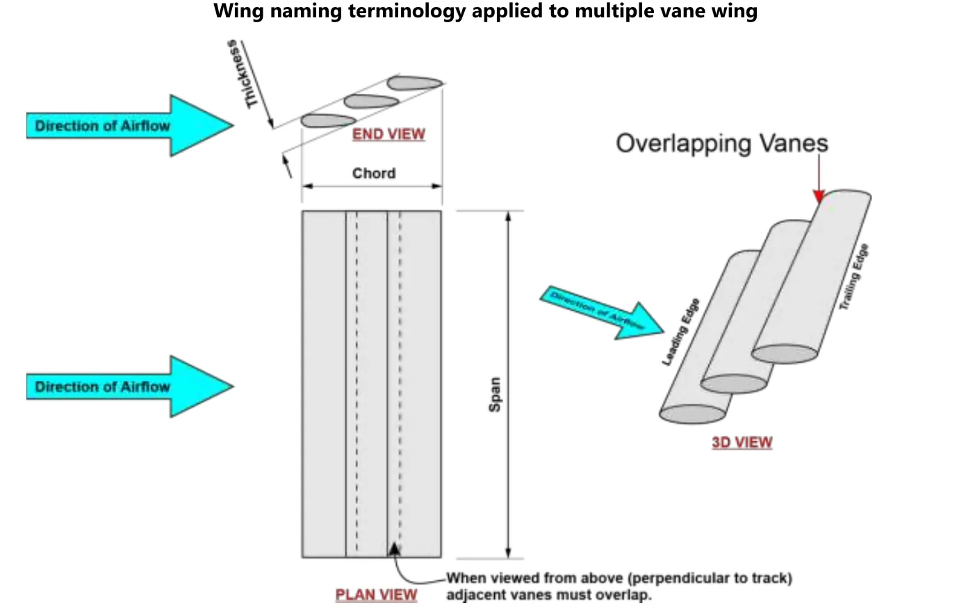
A wing on a STEM Racing™ India car is an aerodynamic feature that permits airflow around its minimum required chord surface including its features of a leading and trailing edge across its minimum required span width. A wing is dimensionally defined by the span, chord and thickness. The vertical cross-sectional shape of the wing, parallel to the direction of car travel, is referred to as an aero-foil.
Wing cross-section / aero-foil naming terminology:
T1.6 Wing support structure and end plate
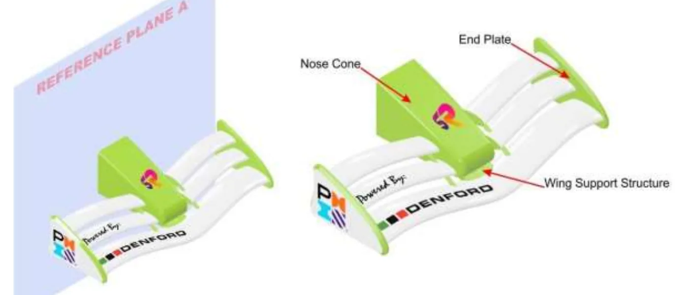
Front Wing support Structure Front wing support structure is a feature forward of reference plane A, that joins a wing(s) to the nose cone.
Rear Wing support Structure Rear wing support structure is a feature rearward of reference plane B, that joins the wing to the car body.
End Plate Any structure that forms part of a wing assembly outside of the minimum wing span.
T1.7 Nose cone
The nose cone is a component of the car, which is used as a wing support structure, that only exists forward of reference plane A. This includes any STEM Racing™ Model Block material or any other materials that continue forward of reference plane A.
T1.8 Wheel
A wheel is a single part or assembly of components, cylindrical in form, with its maximum circumference contacting the track surface, allowing forward motion of the car through rotation.
T1.9 Wheel support system
Wheel support systems are single parts or an assembly of components that connect a wheel to any other part of the car, they MUST be contained within a theoretical cylindrical extrusion defined by the actual diameter of the relative wheels across each axle. These may be sourced from a supplier or manufactured wholly or in part by the team.
T1.10 Tether line guide
A tether line guide is a key safety component which completely surrounds the track tether line so as to safely connect the car to the tether line during races. A tether line guide can be a component sourced from a supplier or manufactured wholly or in part by the team.
T1.11 Surface finish and decals
A surface finish on a STEM Racing™ India car is considered to be any applied visible surface covering, of uniform thickness over the profile of a STEM Racing™ India car assembly component. A decal is material adhered to a component or surface finish. To be defined as a decal, 100% of the area of the adhering side must be attached to a surface. Surface finishes and decals are included when measuring the dimensions of any components they feature on.
T1.12 STEM Racing™ India logo decal
Teams must use a labelled decal to identify Car A and Car B and a blank decal to identify display car(s). The official decals are supplied by STEM Racing India at event registration.
This consists of the STEM Racing™ India logo graphic printed on a black or a white adhesive vinyl with a 1mm contrast keyline border, with a horizontal dimension of 30mm and vertical dimension of 15mm. Teams choose to use either the black or white outlined decal so as to provide maximum contrast to the surface color the decal is being adhered to.
A team can manufacture and fit their own decals, provided they use the official STEM Racing™ India logo decal artwork which can be downloaded from the below link:
https://drive.google.com/file/d/11t56pArfPVFblFcMD7KTnzL9w_gE142e/view?usp=drive_link
Decal designs:

T1.13 Hand finishing
Hand finishing is defined as use of a hand powered device (e.g. abrasive paper) for removing only the irregularities that may remain on a CNC machined surface of the car body. These irregularities are often referred to as ‘machined marks’, any hand finishing must be kept to a minimum.
T1.14 Official STEM RACING™ Model Block
The official STEM Racing™ Model Block Material is a rigid, closed cell foam block processed to the dimensional features as shown by diagrams in the appendix of this document.
IMPORTANT: all cars entered into the STEM Racing™ India National Finals 2025/26 must be manufactured from STEM RACING™ Model Blocks.
T1.15 Engineering drawings
Engineering drawings are CAD produced drawings which should be detailed such that, along with relevant CAM programs, could theoretically be used to manufacture the fully assembled car by a third party. Such drawings MUST include all relevant dimensions and material information.
Where stated, STEM Racing™ India engineering drawings of a readable scale MUST be clearly dimensioned and identified by hatching, shading, block color or boundary line within the engineering drawings to specifically identify and prove compliance for the virtual cargo, front and rear wheel support structures, nose, front and rear wing support structures and front and rear wing surfaces.
Clearly labelled construction or boundary lines are acceptable to define the boundaries between components such as nose cone, wheel support and wing support structures.
Engineering drawings can include: orthographic projection, auxiliary projection, section views, isometric projection, oblique projection, perspective and annotated renderings.
It is recommended to label the relevant technical regulations where appropriate (e.g T9.5.1: 25.0mm) throughout your Engineering drawings; this makes the job of the scrutineer much easier in identifying the different features of your car.
See competition regulations scorecard for mandatory detailed list.
T1.16 Renderings
Renderings are images intended to illustrate the three-dimensional form of an object. These can be generated in isometric projection, oblique projection, or perspective.
T1.17 Reference planes
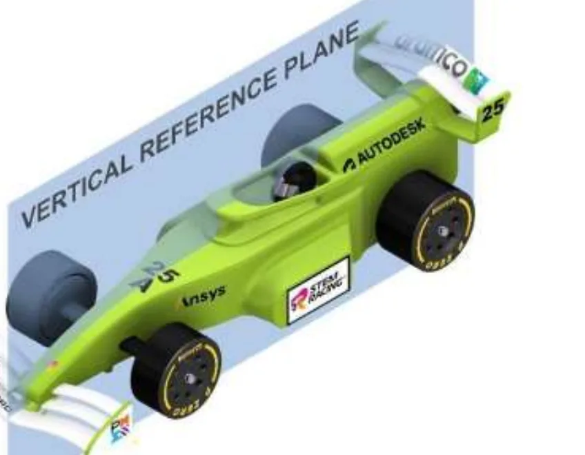
T1.17.1 Vertical reference plane
To assist with describing dimensions, it is assumed that a two-dimensional invisible plane exists along the length of the power unit cartridge chamber center axis and normal to the track surface. This is known as the vertical reference plane.
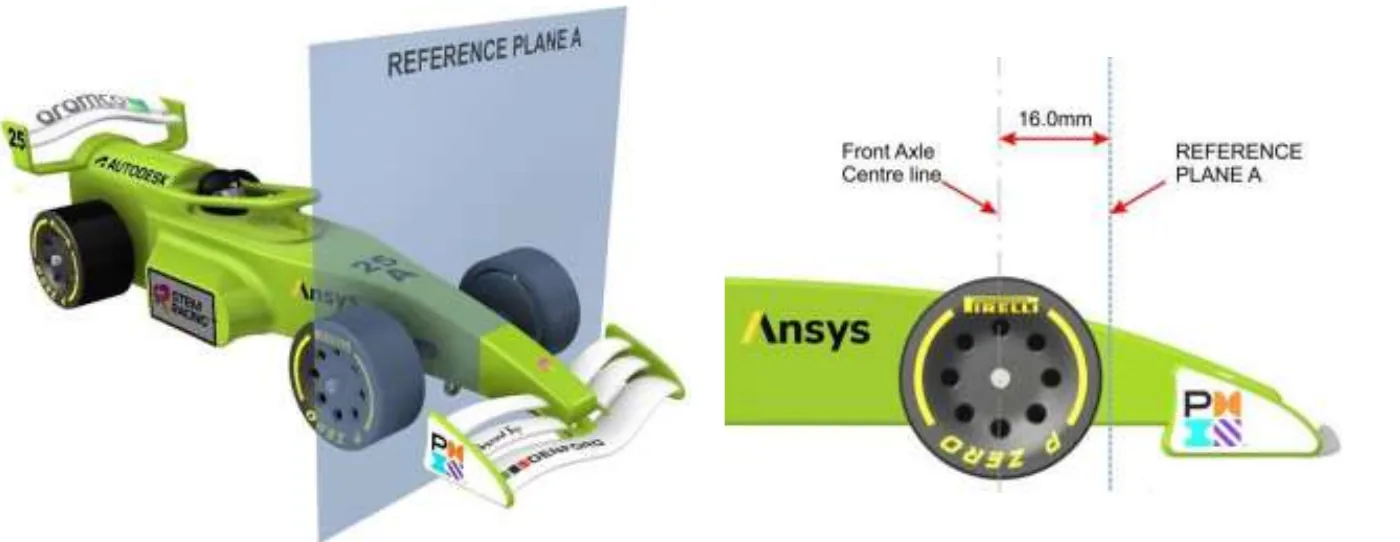
T1.17.2 Reference plane A
To assist with describing dimensions, it is assumed that a two-dimensional invisible plane exists 16.0mm in front of the front axle center line normal to the track surface. This is known as reference plane A.
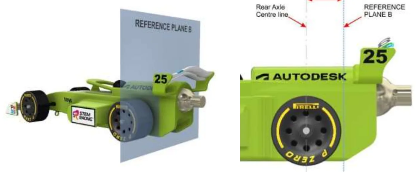
T1.17.3 Reference plane B
To assist with describing dimensions, it is assumed that a two-dimensional invisible plane exists 16.0mm to the rear of the rear axle center line normal to the track surface.
This is known as reference plane B.
T1.18 Additional components
Any component other than those listed in T1.1 will be considered an additional component.
T1.19 Normal
The term ‘normal’ can be used in geometry to describe a line or object that is perpendicular or at 90 degrees to another given object. When referring to the term normal in these regulations it is considered to mean:
- Being at right angles; perpendicular.
- Perpendicular to the direction of a tangent line of a curve or a tangent plane to a surface.
T1.20 Full 8-gram power unit cartridge
A metallic cartridge which contains an 8-gram charge of compressed air. For weights and dimensions refer to appendix v. Official Denford Race Power Pack dimensions.

T1.21 Halo
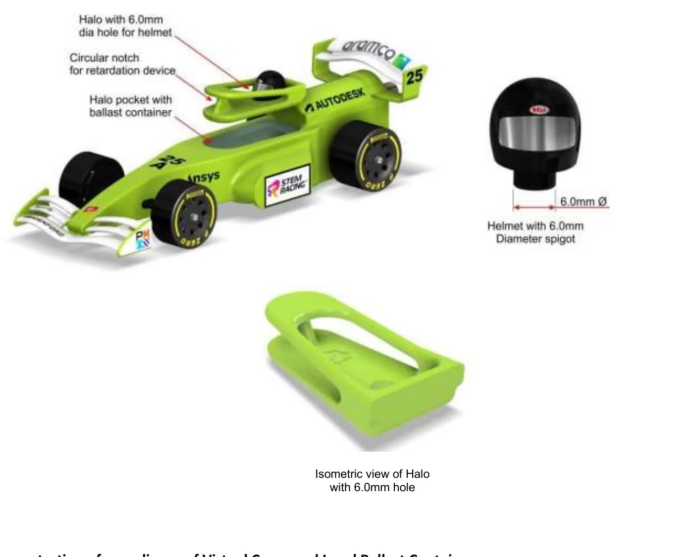
The halo is a driver crash-protection system used in open-wheel racing series, which consists of a curved bar placed to protect the driver's head. The Halo is being introduced to STEM Racing™ India not only to echo real Formula 1® car design but also as a component of a new car deceleration system.
The Halo is available to download as a universal 3D part from the below link:
https://drive.google.com/file/d/1LqT9k6uSwtxeE2QIIyHkdd78VseXGfTt/view?usp=drive_link
The Halo MUST be included in the final car design. Detailed Engineering Drawings are available in appendix ix.

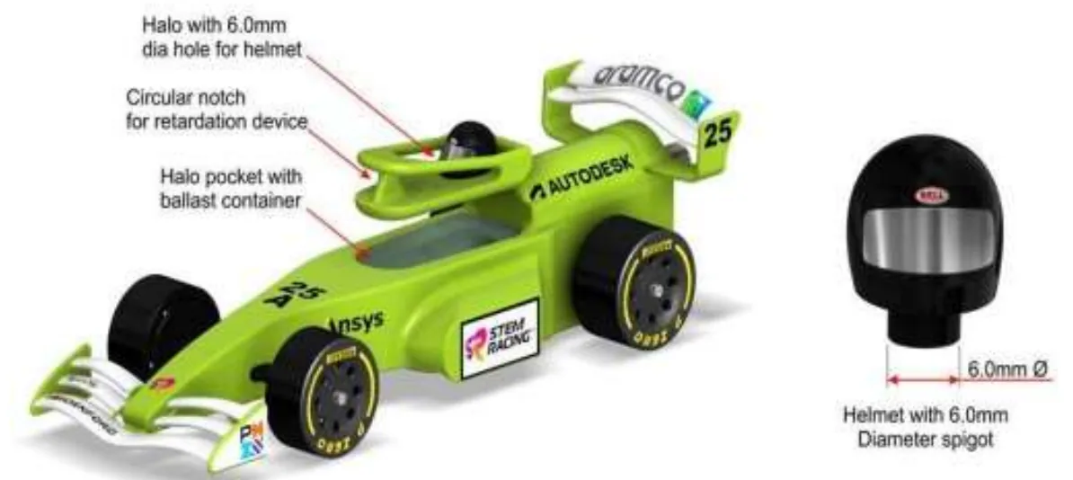
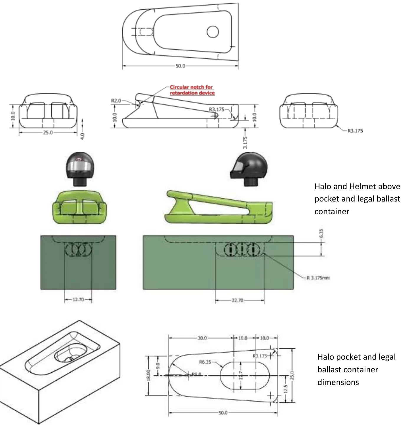
The Halo must be well adhered to the body of the car, to achieve this requires a recess or pocket to match the underside of the Halo in the car body. It has been designed so the required recess or pocket can be manufactured using a 1/4" (6.35mm) ball nose cutter. The Halo and the Helmet are mandatory items and can be made from any material. Please refer to T4.4 for the halo file. Please see Appendix ix for further details.
T1.22 Legal ballast
To help achieve the minimum weight, legal ballast may now be added only to the container under the halo, accessible through the halo/helmet aperture (hole). This is the only permitted location for ballast. The ballast can consist of materials such as fishing lead weights or similar
Article T2 General principles
T2.1 Regulations documents
STEM Racing India, issues the regulations, their revisions and amendments made.
Technical Regulations - this document. The Technical Regulations document is mainly concerned with those regulations that are directly related to STEM Racing™ India car design and manufacture. Technical regulation article numbers have a ‘T’ prefix.
Competition Regulations – a document separates to this one which is mainly concerned with regulations and procedures directly related to judging and the competition event. Competition Regulation article numbers have a ‘C’ prefix.
T2.2 Interpretation of the regulations
The text of a regulation and any related definitions should be considered together for the purpose of interpretation.
Text clarification - any questions received that are deemed by STEM Racing India to be related to regulation text needing clarification will be answered by STEM Racing India The question received, along with the clarification provided by STEM Racing India, will be published to all competing teams at the same time.
T2.3 Amendments to the regulations
Any amendments will be announced and released by STEM Racing India by email notification to all the Teams. Any amended text will be indicated thus (using red underlined text).
T2.4 Classification of regulations
The technical regulations are classified as either: GENERAL, SAFETY, PERFORMANCE.
| GENERAL | SAFETY | PERFORMANCE |
|---|---|---|
| Regulations that shape the way the car fundamentally looks and works, vital to the style of a STEM Racing™ car. | Mandatory rules that govern the safe running of the car. Cars must meet these rules to be considered ‘safe to race’. | Rules that have a direct impact on the performance of the vehicle, these typically carry the heaviest penalties. |
If a race car is judged as being NON-COMPLIANT with any Performance regulation they will be INELIGIBLE for the awards of: ‘Fastest Car’ and ‘Best Engineered Car’. All Performance regulations are highlighted in yellow throughout this document.
T2.5 Compliance with regulations
Points are deducted for non-compliance with the technical regulations as per the penalties as defined in this document. Both race cars are assessed during Specification Judging and points will be deducted for any infringements on either car. These penalties are only applied once, per infringement, per car.
After initial Specification Judging any team with “safety” infringements will be given a 10-minute service session. See competition regulations for more information.
Proportional penalties will be applied to the following regulations:
T3.4, T3.5, T3.6, T3.7, T5.2, T5.6, T7.2, T7.3, T7.4, T7.5, T7.11, T8.6, T8.6.2, T8.6.3, T9.5.1, T9.5.2, T9.5.3, T9.5.4
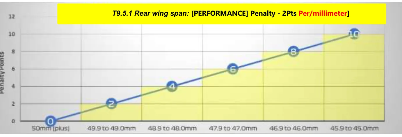
The penalty applied increases proportionally as the margin of non-compliance with the absolute minimum/maximum dimension increases by rounding up the non-compliance to the next complete unit of measure (1.0mm or 1.0g). The penalty is applied once for every complete unit outside of the absolute minimum/maximum dimension. For example:
T2.6 Design ideas and regulation compliance questions
Teams are not permitted to seek a ruling from STEM Racing India or any competition officials or judges before the event as to whether a design idea complies with these regulations, any regulatory communication between teams and ICCs or teachers is only for guidance, rulings will only be made by the official judges at the National Finals event. Design compliance to the regulation’s forms part of the competition. As in Formula 1® innovation is encouraged and STEM Racing™ India teams may also find ways of creating design features that push the boundaries of the regulations in order to get an extra competitive edge.
T2.7 Measurements
All dimensions and weights are presented as absolute minimum or maximum, unless stated otherwise. For example:
| MIN Weight | MIN Dimension | MAX Dimension |
|---|---|---|
| Absolute Min: 50.0g | Absolute Min: 26.0mm | Absolute Max: 34.0mm |
| 50.0g - PASS | 26.0mm - PASS | 34.0mm - PASS |
| 49.9g - FAIL | 25.9mm - FAIL | 34.1mm - FAIL |
*Note – Important regulations for Main Car Body (excluding nose cone & rear wing) –
- The Main Car Body, including the support structure, must have a maximum overall length of 205mm to meet the required design specifications and competition standards.
- Absolute Max: 205.0mm
- The Main Car Body must maintain a minimum thickness of 3.5mm at every point to ensure structural integrity and compliance with competition regulations.
- Absolute Min: 3.5mm
Dimensional measures - all car component dimensions or weight are inclusive of any applied paint finish or decal. A series of specially manufactured gauges will be used to broadly verify dimensional compliance. Accurate measuring tools, such as vernier calipers, will then be used to closely inspect any dimensions found to be close to the dimensional limits per the initial gauge inspection. IMPORTANT: Some regulations are assessed with a full 8g race cartridge fully inserted into the cartridge chamber. For compliance with these regulations, the static weight distribution of the car must be such that the car is capable of resting on all four (4) wheels without any outside assistance.
Weight measures – all weight measurements will be made using the STEM Racing India calibrated electronic competition scales.
T2.8 Benefit of doubt
The chair of judges will, where appropriate, seek to use ‘benefit of doubt’ when the assessment of compliance is marginal or unclear. In this situation, teams will be given the benefit of doubt rather than a firm penalty if a penalty cannot be clearly measured or identified.
T2.9 Spirit of the competition
Teams are expected to act in the spirit of the competition, both before and during the STEM Racing™ India National Finals. Any team or individual team member deemed by the chair of judges to be acting outside of the spirit of the competition, can be removed from certain or all aspects of the competition. For example, a team or individual team member attempting to abuse the technical regulations to their advantage may, at the discretion of the chair of judges, be removed from racing and receive no points for this activity. A team or individual team member deemed to be acting in an unsportsmanlike manner towards another team or other persons may be removed from some or all judging areas.
The spirit of the competition is simple; embrace and respect the rules and regulations, do your very best to compete legally and fairly, while contributing positively to the STEM Racing™ India National Finals. Make friends, create positive relationships, network professionally and enjoy yourselves.
T2.10 Originality of work
STEM Racing India welcomes and endorses innovation and does not consider that plagiarism should play any part in any of the disciplines that make up the competition.
Competing teams at all levels of the competition that intentionally plagiarize any part of their assessed work, undermines the credibility and integrity of the STEM Racing™ India challenge and the spirit of the competition.
At the STEM Racing™ India National Finals 2025/26, STEM Racing™ India shall be implementing various originality detection methodologies and requesting all competing teams to submit an originality declaration. Further details and associated penalties will be explained in detail in the STEM Racing™ India National Finals 2025/26 competition regulations.
Article T3 Fully assembled car
T3.1 Design and manufacture
[GENERAL | Penalty – 5pts each]
All STEM Racing™ India cars must be designed and engineered using CAD (Computer Aided Design) and CAM (Computer Aided Manufacture) technology. CAD software used should provide for 3D part modelling, assembly and 3D realistic rendering. We recommend the use of Autodesk Fusion 360 software. The CAM package should allow students to simulate CNC machining processes so they can show evidence of these in their portfolio. We recommend the use of Denford QuickCAM PRO software.
The body of all STEM Racing™ India cars must be manufactured via material removal using a CNC router/milling machine. We recommend all teams use a Denford CNC Router. This manufacturing process should occur at your school/college or at a designated manufacturing center/partner site.
An official STEM Racing™ holographic sticker from the official STEM Racing™ Model Block for each car must be submitted on the project element submission sheet at the National Finals event registration. STEM Racing India stickers will also be permitted.
The individual components of both race cars must be designed with identical geometry.
T3.2 Safe construction
[SAFETY | Penalty – 10pts each]
Specification judging - all submitted cars will be inspected closely to ensure that they are engineered and constructed safely for the purpose of racing. If the judges rule an aspect of either race car to be unsafe for racing, the team will be required to carry out repairs / modifications to the car(s). Any such repair work will result in a penalty of 10 points per unsafe car.
During racing – the race officials will routinely inspect cars for safety during scheduled races. If the officials rule a car to be unsafe, a penalty of 10 points will be imposed at the discretion of the Chair of Judges. The team may repair the car as per the Competition Regulations – C10 Car Repairs and Servicing.
T3.3 Defined features
[PERFORMANCE | Penalty – 20pts]
The car assembly must only consist of components listed in ARTICLE T1.1.
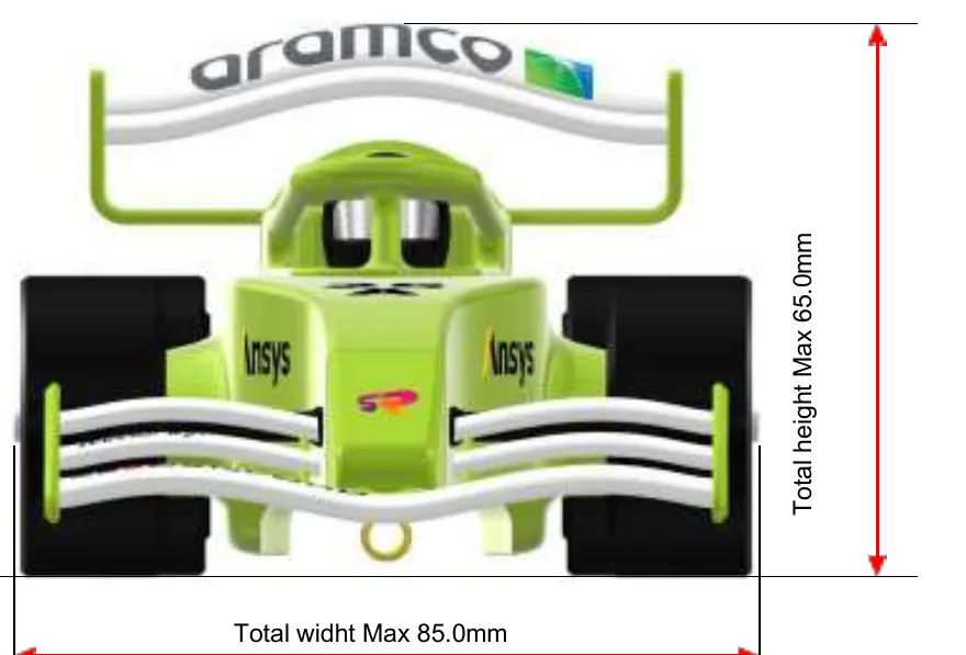
T3.4 Total width
[GENERAL | Penalty – 5pts per millimeter]
Total width is the maximum assembled car width, measured normal to the vertical reference plane, between the outer edges of the widest feature of the car assembly.
Absolute Min: 65.0mm / Absolute Max: 85.0mm
T3.5 Total height
[GENERAL | Penalty – 5pts per millimeter]
Total height is the maximum assembled car height, normal to the vertical reference plane, between the track surface and the highest feature of the car assembly. This is measured with a full 8g power unit cartridge inserted into the cartridge chamber with the car sitting on all four (4) wheels with no outside assistance.
Absolute Max. 65.0mm
T3.6 Total weight
[PERFORMANCE | Penalty – 10pts per gram]
Total weight is the weight of the car excluding a power unit cartridge. If ruled underweight at car registration and confirmed during initial specification judging using the official competition scales, the above points penalty will be applied. No car will race underweight and ballast will be added to the underside of the car at 0.2g for every 0.1g underweight.
Absolute Min: 50.0g
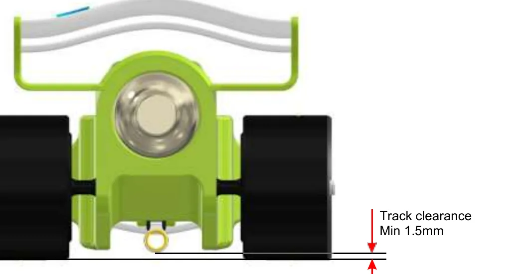
T3.7 Track clearance
[GENERAL | Penalty – 10pts per millimeter]
Track clearance is the distance between track surface and any car component as listed in T1.1, except wheels. Measured normal to the track surface. This is measured with a full 8g power unit cartridge inserted into the cartridge chamber with the car sitting on all four (4) wheels with no outside assistance.
Absolute Min: 1.5mm
T3.8 Status during racing
[GENERAL | Penalty – 5pts]
The car assembly must be designed so that no items other than those listed in T3.9, or power unit cartridges are removed, replaced or added to the assembly during scheduled race events.
T3.9 Replacement components
[GENERAL]
Any spare / replacement components should be identical in design and geometry to those fitted to the car and must be submitted with the cars at registration. Only the following spare / replacement components are permitted:
| Component | Max Quantity |
|---|---|
| Nose cone & front wing assembly | 2 |
| Rear wing assembly | 2 |
| Front wheels | 4 |
| Front wheel support structure | 2 |
| Rear wheels | 4 |
| Rear wheel support structure | 2 |
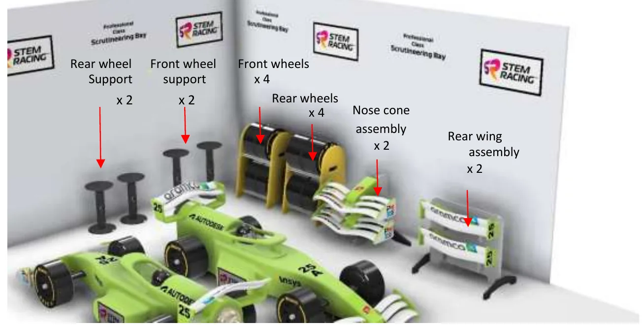
Submitted components – [GENERAL] Only submitted replacement components that are determined by the judges to be identical in design and geometry to those fitted to the cars will be allowed to be used during track repairs or post-race servicing.
Introduced components - [GENERAL | Penalty – 5pts per component] If any other items need to be introduced for car repairs a 5pt penalty will be incurred per component item.
Article T4 Body
T4.1 Body construction
[GENERAL | Penalty – 20pts]
A single continuous piece of CNC manufactured STEM Racing™ Model Block material must exist rear of the reference plane A, encompassing both the virtual cargo and power unit cartridge chamber.
T4.2 Virtual cargo
[PERFORMANCE | Penalty – 25pts]
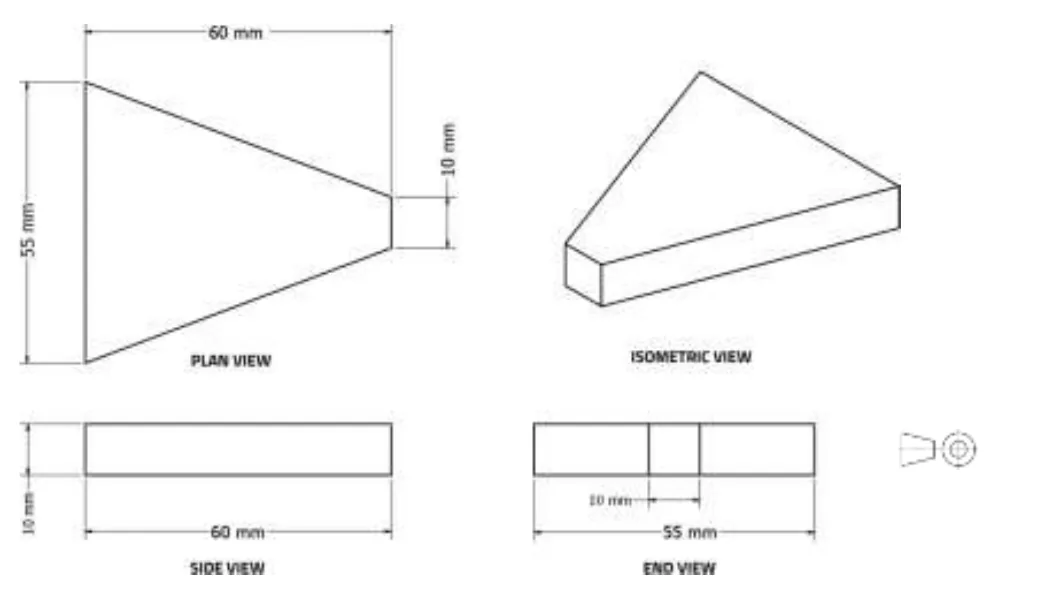
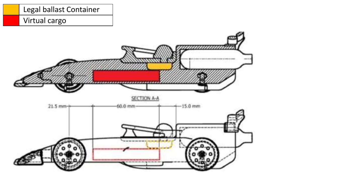
A virtual cargo must be completely encompassed by the body and be wholly positioned between the front and rear wheel center lines. The virtual cargo must have minimum dimensions as shown below, with its top surface located symmetrically about and positioned normal (90 degrees) to the vertical reference plane. The virtual cargo may also share common faces with the car body. All dimensions shown are absolute minimum. The Virtual Cargo can coincide with the legal ballast container but not the halo pocket.
T4.3 Virtual cargo identification
[GENERAL | Penalty – 5 pts]
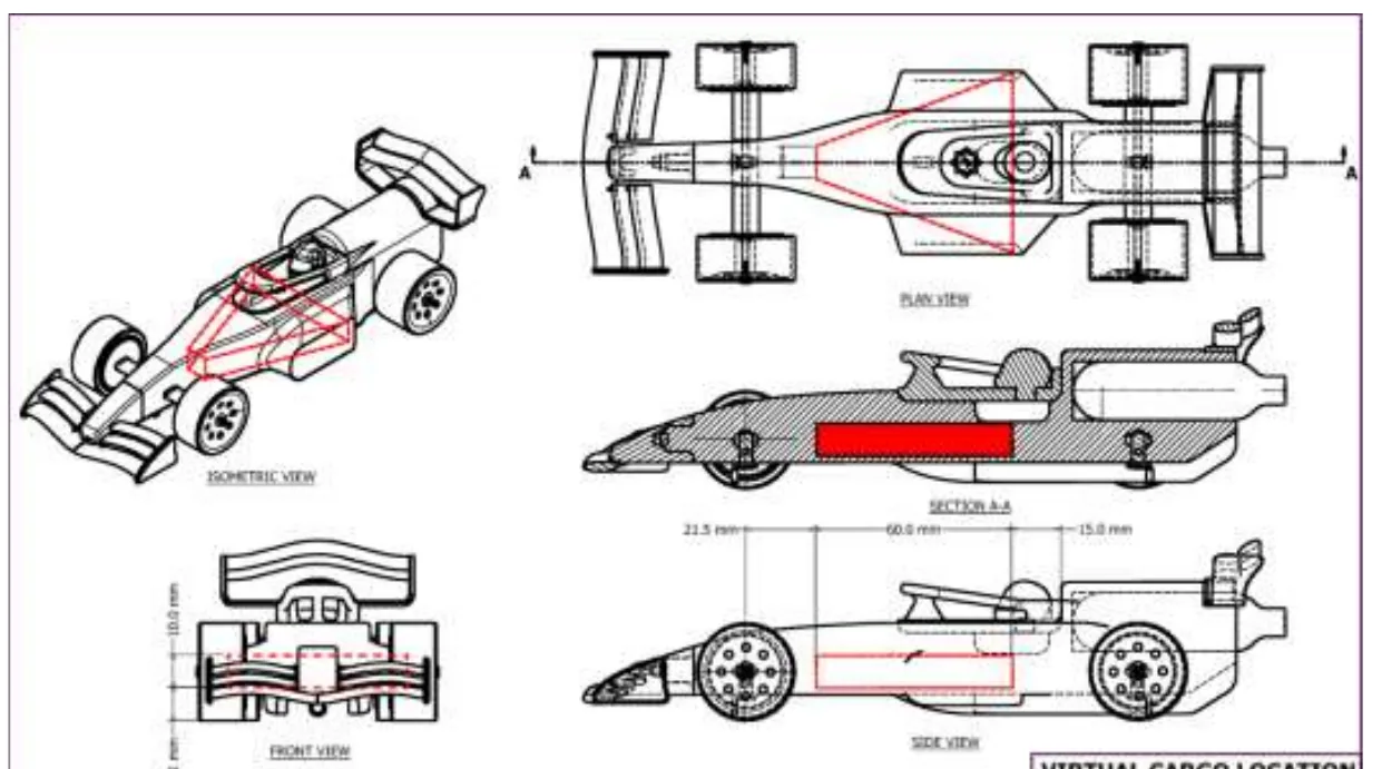
The virtual cargo location and compliance MUST be clearly dimensioned (such as from either the front or rear axle center lines and height above the track). The virtual cargo MUST be identified by hatching, shading or block color, or outlined with a contrasting color line within the engineering drawings submitted for scrutineering. Please refer to the example diagram below, showing the virtual cargo clearly highlighted in red:
T4.4 Halo
Halo – [PERFORMANCE | Penalty – 10 pts] The Halo (refer ARTICLE T1.21) MUST be included in the car design without any dimensional or surface profile changes. The file can be downloaded from
https://drive.google.com/file/d/1LqT9k6uSwtxeE2QIIyHkdd78VseXGfTt/view?usp=drive_link
Please see appendix ix for detailed dimensions.

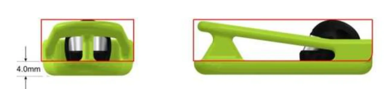
Halo visibility front and side views – [GENERAL | Penalty – 10 pts] Visibility of the Halo must not be physically obstructed by any other component when viewed in the front or side views.
SIDE VIEW When viewed from the side, everything inside the red outline MUST be visible.
FRONT VIEW When viewed from the front, everything inside the red outline MUST be visible.
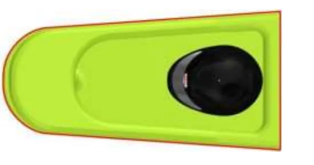
Halo visibility top view – [GENERAL | Penalty – 10 pts] The Halo must not be physically obstructed in the plan view except by the helmet.
TOP VIEW When viewed from the top, everything inside the red outline MUST be visible.
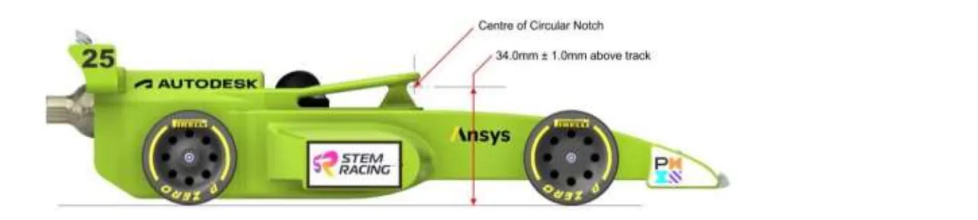
Halo circular notch height– [SAFETY | Penalty – 5pts] To be effective the center of the Circular Notch must be 34.0mm (±1.0mm) above the track surface. To achieve this the bottom of the halo pocket must be 24.0mm and parallel to the track surface in the assembled car.
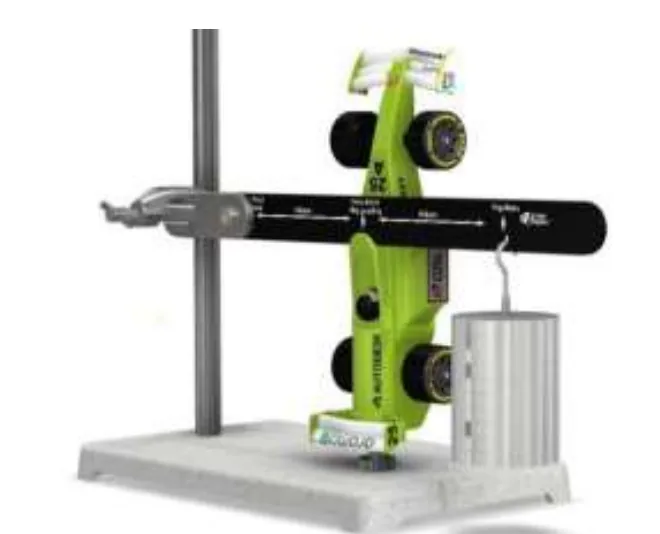
Halo Safety Test– [SAFETY | Penalty – 5pts] With the car supported on a power unit cartridge a 1kg load will be suspended to give a loading of 2kg (to be reviewed) at point of contact on the Halo circular notch.
T4.5 Helmet
[GENERAL | Penalty – 5pts]
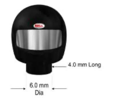
The Helmet is a standard part designed by STEM Racing™ that MUST be included in the car design without any dimensional changes. The Helmet is available to download as a universal 3D part from the below link:
https://drive.google.com/file/d/1U3kd9Qh7LR_hv_htGgKA1zm3EyGKUKOs/view?usp=drive_link
The helmet may be manufactured out of any material.
We suggest that the helmet be painted in the team’s country or hero driver colors
T4.6 STEM Racing™ India logo decal location
[GENERAL | Penalty – 5pts]
A STEM Racing™ India logo decal (refer ARTICLE T1.12) must be wholly adhered to each side of the car, and be 100% visible in the respective side view. Teams may manufacture their own decals but must use the artwork supplied by STEM Racing India.

T4.7 Team number
[GENERAL | Penalty – 2pts]
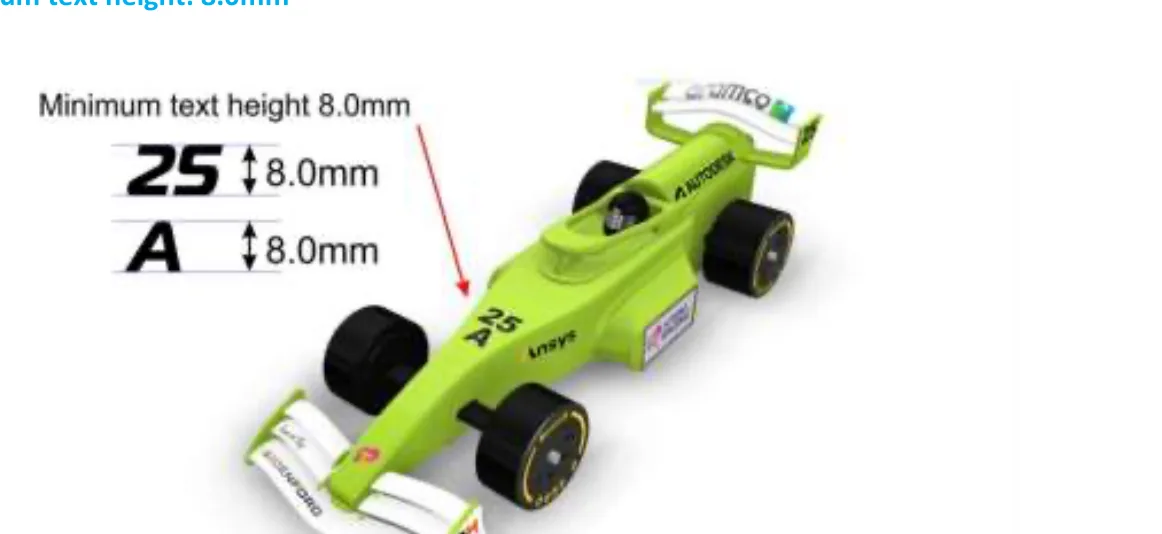
After registering for the National Finals event each team shall be issued with their official team number. This must be displayed on the car body between the front edge of the halo and reference plane A. The number should be clearly visible in the plan view and a minimum text height of 8mm. If a team submits their car without the team number, then one will be provided at the world finals event.
Teams may additionally include the team number elsewhere on the car such as the rear wing endplates.
Minimum text height: 8.0mm
T4.8 Decal thickness
[GENERAL | Penalty – 5pts]
This is measured as the total thickness of any decal, excluding any surface finishes.
Absolute Max: 0.5mm
Article T5 Power unit cartridge chamber
T5.1 Diameter
[SAFETY | Penalty – 5pts]
This is the diameter of the power unit cartridge chamber, measured at any point through its minimum depth.
Absolute Min: 18.0mm / Absolute Max: 18.5mm
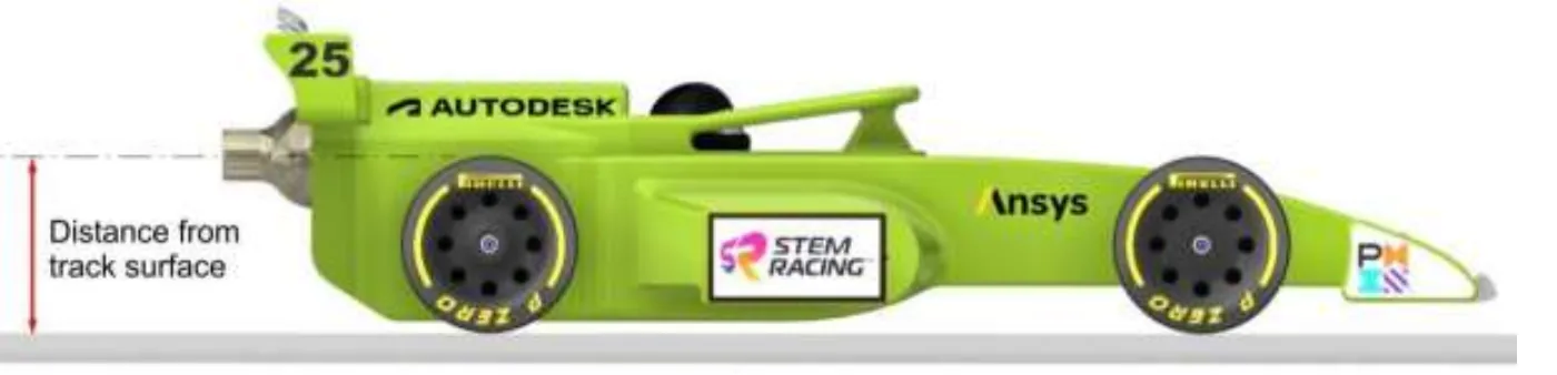
T5.2 Distance from track surface
[GENERAL | Penalty – 5pts per millimetre]
This is measured with a full 8g power unit cartridge inserted into the cartridge chamber, from the rear center of the power unit cartridge to the track surface, measured normal to the track surface with the car sitting on all four (4) wheels with no outside assistance.
Absolute Min: 30.0mm / Absolute Max: 40.0mm
T5.3 Depth
[SAFETY | Penalty – 5pts]
The depth of the chamber is measured parallel to the vertical reference plane anywhere around the chamber circumference from the opening to the chamber end.
Absolute Min: 45.0mm / Absolute Max: 58.0mm
T5.4 Max angle of chamber
[SAFETY | Penalty – 5pts]
The absolute maximum angle of the chamber, parallel to the track surface. This is measured with a full 8g power unit cartridge inserted into the cartridge chamber with the car sitting on all four (4) wheels with no outside assistance.
Absolute Min: -3° Absolute Max: 3°
T5.5 Chamber safety zone
[SAFETY | Penalty – 10pts]
A safety zone of STEM Racing™ Model Block material with a minimum thickness of 3.5mm must be maintained around the minimum chamber depth (see T5.3). The chamber safety zone and connection to the car body will be assessed and if determined below the minimum thickness, may be considered a safety issue at the judge’s discretion, see ARTICLE T3.2.
IMPORTANT: the entire circumference and depth of the power unit cartridge chamber must not be intersected by any object.
Absolute Min: 3.5mm
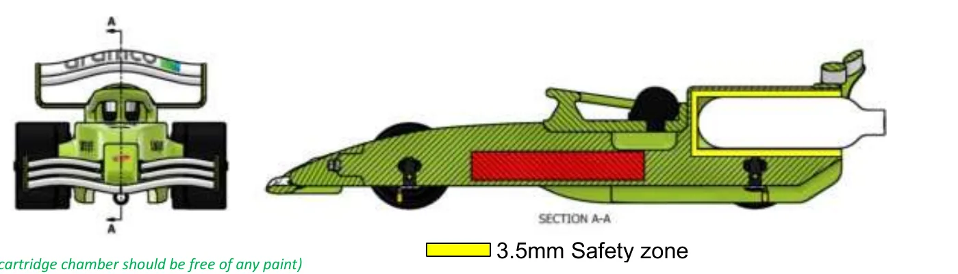
(The cartridge chamber should be free of any paint)
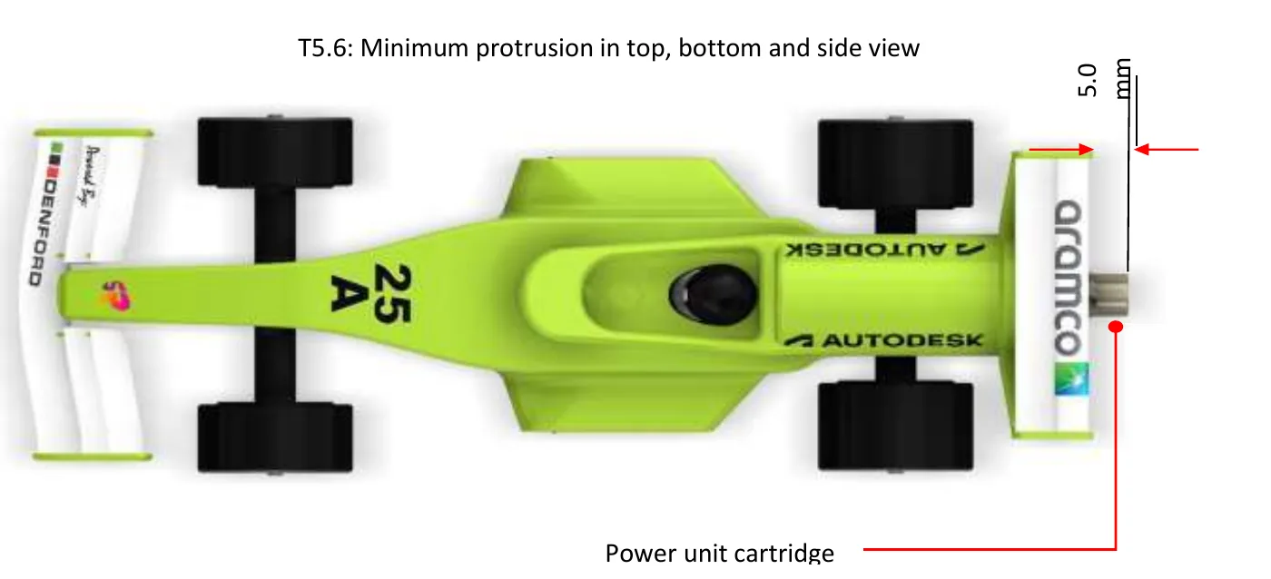
T5.6 Power unit cartridge visibility
[PERFORMANCE | Penalty – 10pts per millimeter]
When fully inserted, the power unit cartridge must protrude a minimum of 5.0mm from the rear of the car and be visible in its entirety when viewed radially around the longitudinal centerline of the power unit cartridge.
Absolute Min: 5.0mm
Article T6 Tether line guides
T6.1 Location
[SAFETY | Penalty – 10pts]
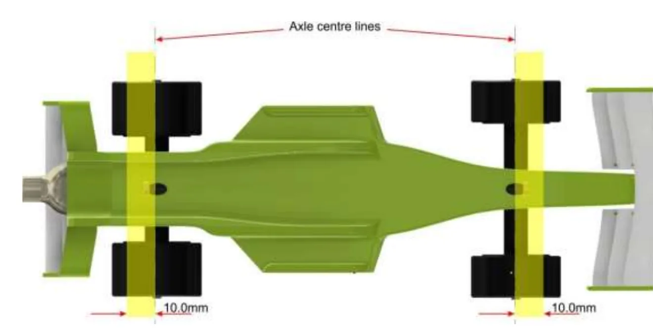
Each car must have only two (2) firmly secured tether line guides, one on or up to 10.0mm in front of the front axle center line and one on or up to 10.0mm behind the rear axle center line of the car. The track tether line must only pass through the two tether line guides during racing.
T6.2 Internal dimension
[SAFETY | Penalty – 5pts]
This is the minimum and maximum internal measurement of the opening within the guide, which the tether line passes through. This will be measured using a 3.5mm and/or 6.0mm diameter tool.
Absolute Min: 3.5mm / Absolute Max: 6.0mm
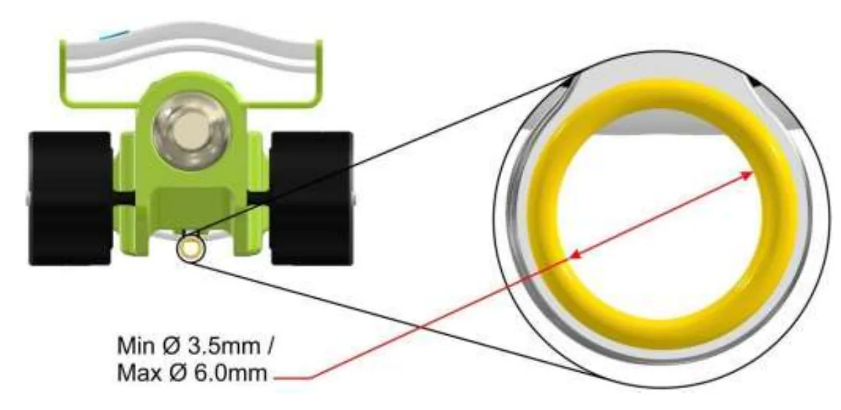
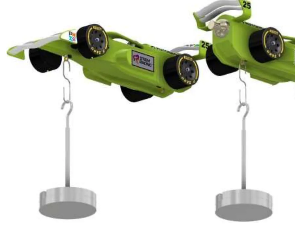
T6.3 Tether line guide safety
[SAFETY | Penalty – 10pts]
The guide holes must be completely closed to prevent the tether line from slipping out during racing. The construction of the tether line guides will be closely examined in relation to safety, please refer to ARTICLE T3.2 for more information. The guides must be robust so as to prevent the diameter or shape changing during racing. The below tether line guide test will be conducted during scrutineering. A 200g weight will be suspended from each tether line guide to check the guides are securely fitted to the car and safe to race.
Article T7 Wheels and wheel support structures
T7.1 Number and location
[GENERAL | Penalty – 25pts]
The car assembly must include four (4) cylindrical wheels, a maximum of two (2) at the front and a maximum of two (2) at the rear. Opposing wheels must share a common center line / axis.
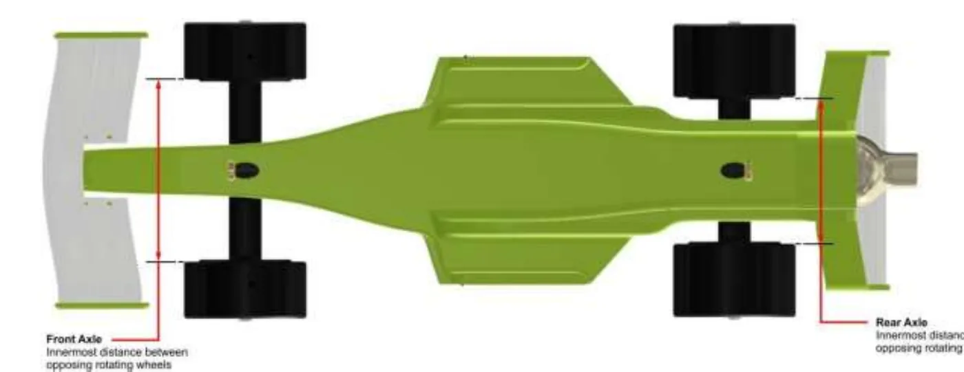
T7.2 Distance between opposing wheels
[PERFORMANCE | Penalty – 2.5pts per millimeter per axle]
This is measured as the innermost distance of the rotating wheel components (other than a rotating axle) between the two (2) opposing wheels measured parallel to the track surface.
Front Axle - Absolute Min: 38.0 mm
Rear Axle - Absolute Min: 30.0 mm
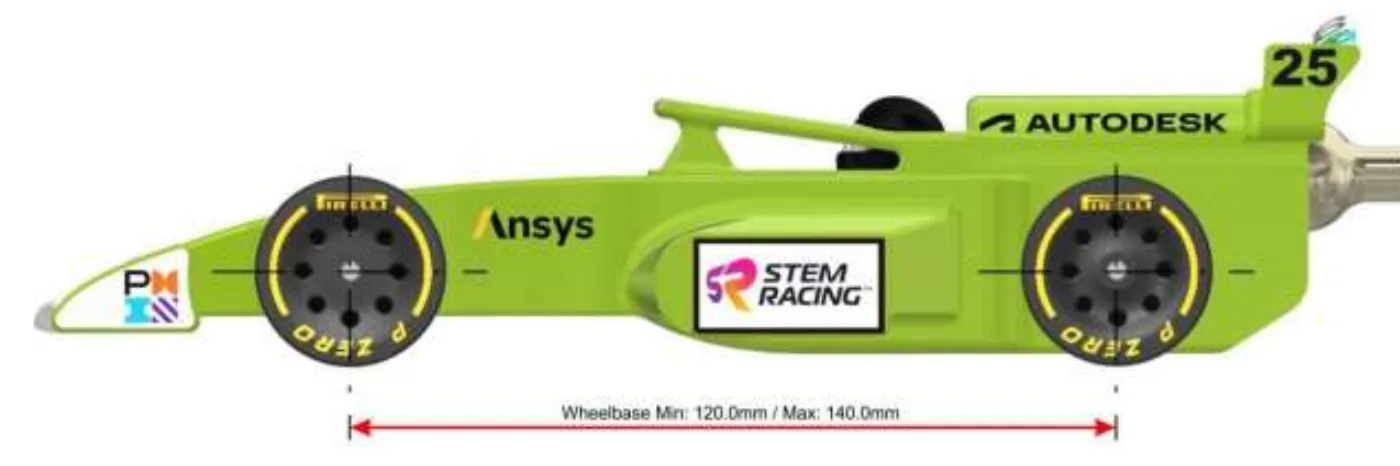
T7.3 Wheelbase
[PERFORMANCE | Penalty –5pts per millimeter]
The wheelbase of the vehicle is the distance between the center line of the front and rear wheels as viewed in the side view.
Absolute Min: 120.0mm / Absolute Max: 140.0mm
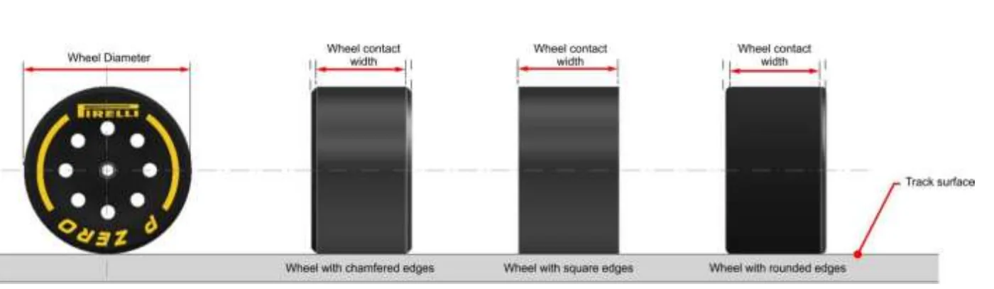
T7.4 Track contact width
[PERFORMANCE | Penalty – 2.5pts per millimeter per wheel]
This is measured along the surface of the wheel that makes constant contact with the track surface, excluding any chamfers or fillets.
If only one wheel per axle is outside of the minimum or maximum dimension, the point penalty will stand but the regulation is reclassified as General.
Front wheels - Absolute Min: 13.0mm
Rear wheels - Absolute Min: 17.0mm
T7.5 Diameter
[PERFORMANCE | Penalty – 2.5pts per millimeter per wheel]
This is the wheel diameter measured across the minimum track contact width rolling surface.
If only one wheel per axle is outside of the minimum or maximum dimension, the point penalty will stand but the regulation is reclassified as General.
Absolute Min: 28.0mm / Absolute Max: 32.0mm
T7.6 Race track contact
[PERFORMANCE | Penalty – 2.5pts per wheel]
All four (4) wheels must touch the racing surface at the same time across the full track contact width, measured with a full power unit cartridge inserted with the car sitting on all four (4) wheels with no outside assistance. Race track contact must be maintained prior to car launch and during racing.
T7.7 Rolling surface
[PERFORMANCE | Penalty – 2.5pts per wheel]
The wheel diameter must be consistent across the track contact width. (i.e. no tread like features are permitted)
T7.8 Rotation
[PERFORMANCE | Penalty – 5pts per wheel]
To facilitate forward motion of the car during racing all (4) wheels must rotate freely about their axis using a 3° maximum inclined surface.
Absolute Max: 3°
T7.9 Visibility in top and bottom views
[PERFORMANCE]
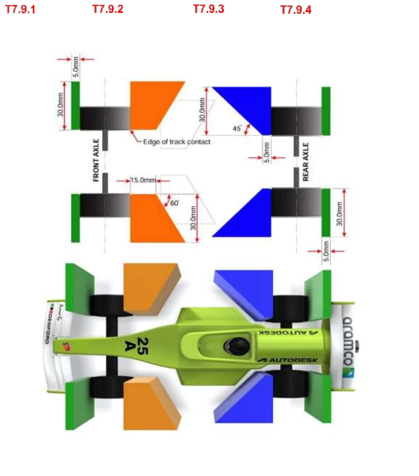
The visibility of all wheels must not be physically obscured by any component of the car in the car’s top and bottom elevation views. Car body or any other components must not exist within the dimensions illustrated below. These dimensions must exist from the inside edges of each wheels’ track contact width to the extreme width of the car assembly and a height from track surface of 65.0mm. This is measured, parallel to the vertical reference plane and track surface. Please also refer to T8.6 and T9.6 – Clear Airflow.
| Regulation | Location | Dimension | Penalty |
|---|---|---|---|
| T7.9.1 | In front of front wheels | Absolute Min: 5.0mm | 2.5pts |
| T7.9.2 | Behind front wheels | Absolute minimum dimensions on diagram below | 5pts |
| T7.9.3 | In front of rear wheels | Absolute minimum dimensions on diagram below | 5pts |
| T7.9.4 | Behind rear wheels | Absolute Min: 5.0mm | 2.5pts |
Scrutineering tools used to define these clearances will be manufactured to dimensions as illustrated below.
T7.10 Visibility in side views
[PERFORMANCE | Penalty – 10pts per wheel]
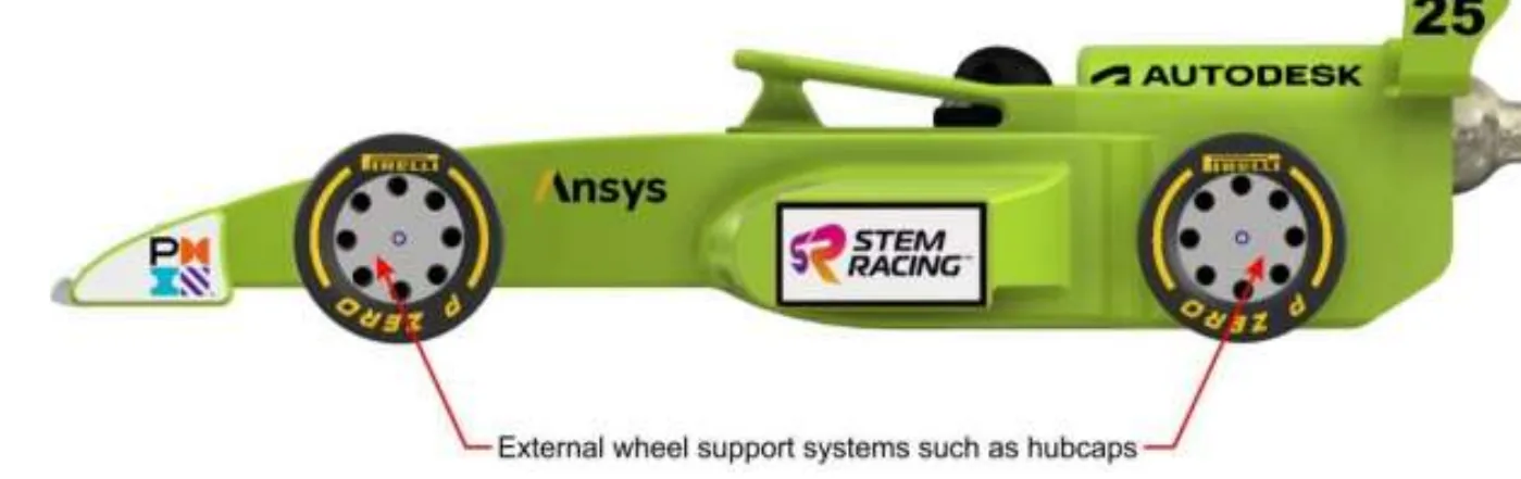
The visibility of all wheels must not be physically obscured by any component of the car with the exception of any wheel support systems, in the car’s side elevation views.
T7.11 Visibility in front view
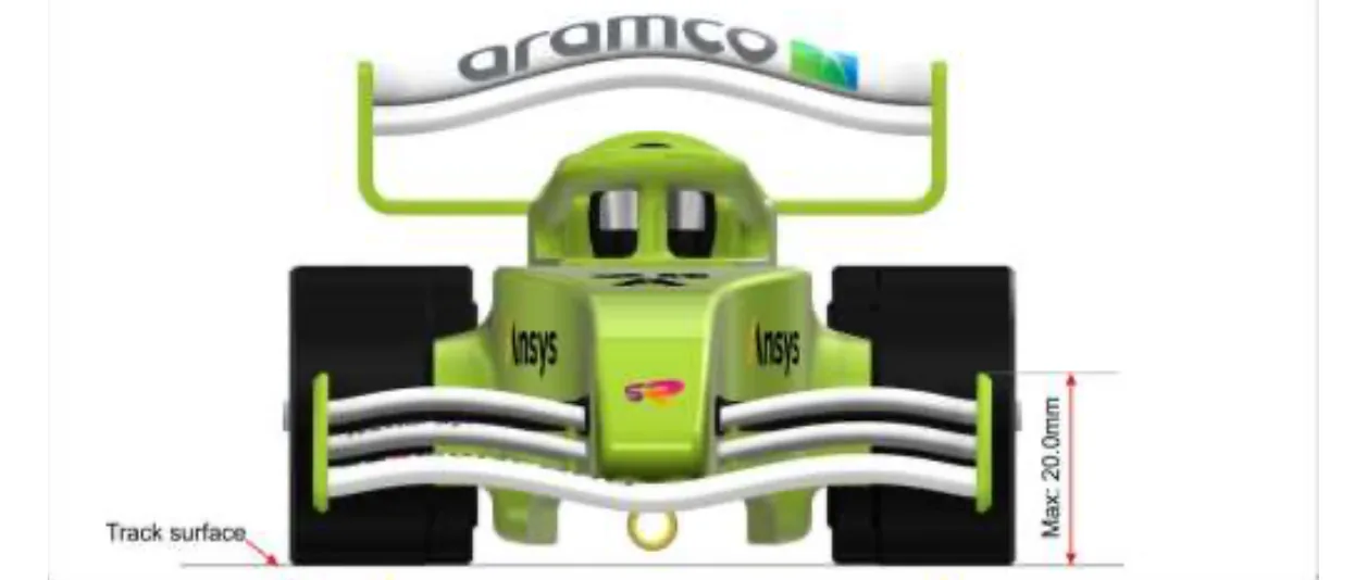
[PERFORMANCE | Penalty – 10pts per millimetre]
The visibility of the front wheels in the car’s front view may only be physically obstructed to a height of 20.0mm from the track surface. This is measured with a full 8g power unit cartridge inserted into the cartridge chamber with the car sitting on all four (4) wheels with no outside assistance.
Absolute Max: 20mm
T7.12 Wheel support
[GENERAL | Penalty – 5pts each]
Wheel support systems: Wheel support systems may only exist within the cylindrical volume generated through the diameter of the two (2) opposing wheels. Refer to ARTICLE T3.8 Track clearance.
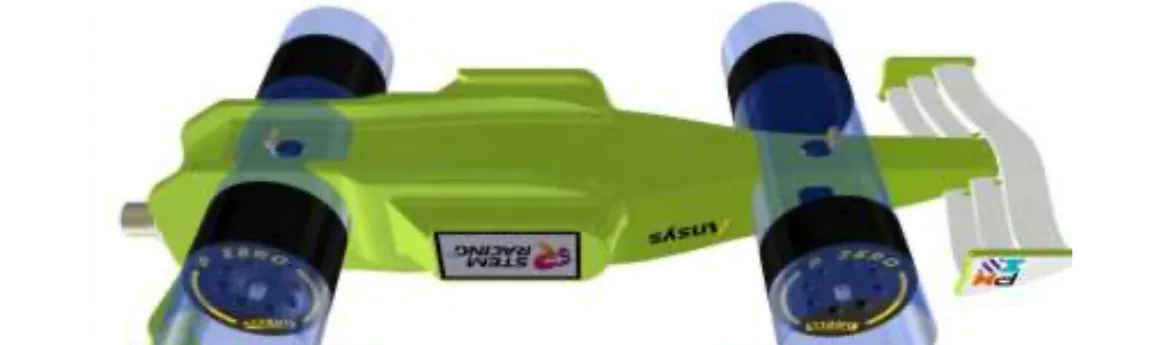
Wheel support systems identification: The surfaces defining the wheel support structures MUST be dimensioned and identified clearly by hatching, shading or block color within the engineering drawings submitted for scrutineering. (Construction lines are acceptable to define the boundaries between components such as nose cone and wing support structures.) Also refer to the definition in ARTICLE T1.15 for guidance on annotating these features in your Engineering Drawings.
T7.13 Wheel safety test
[SAFETY | Penalty – 2.5pts per wheel]
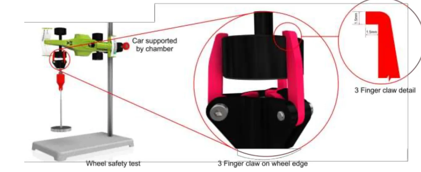
To prevent wheel detachment during racing and encourage good engineering practice a wheel safety test will be carried out.
The wheels must be robust so as to prevent the diameter or shape changing during racing. The below wheel test will be conducted during scrutineering. A 100g weight will be suspended from each wheel.
To allow for this wheel safety test a minimum clearance (see below) is required from the inner corner of the wheel to the car body.
Article T8 Nose, front wing, end plates and wing support structures
T8.1 Nose, front wing, end plates and wing support structure identification
[GENERAL | Penalty – 5pts]
The surfaces defining the nose, front wing(s), end plates and wing support structures must be dimensioned and identified clearly by hatching, shading or block color within the engineering drawings submitted for scrutineering. (Clearly labelled construction lines are acceptable to define the boundaries between components such as nose cone and wing support structure). Also refer to the definition in ARTICLE T1.15 for guidance on annotating these features in your Engineering Drawings.
T8.2 Nose cone assembly dimension
[GENERAL | Penalty – 5pts each]
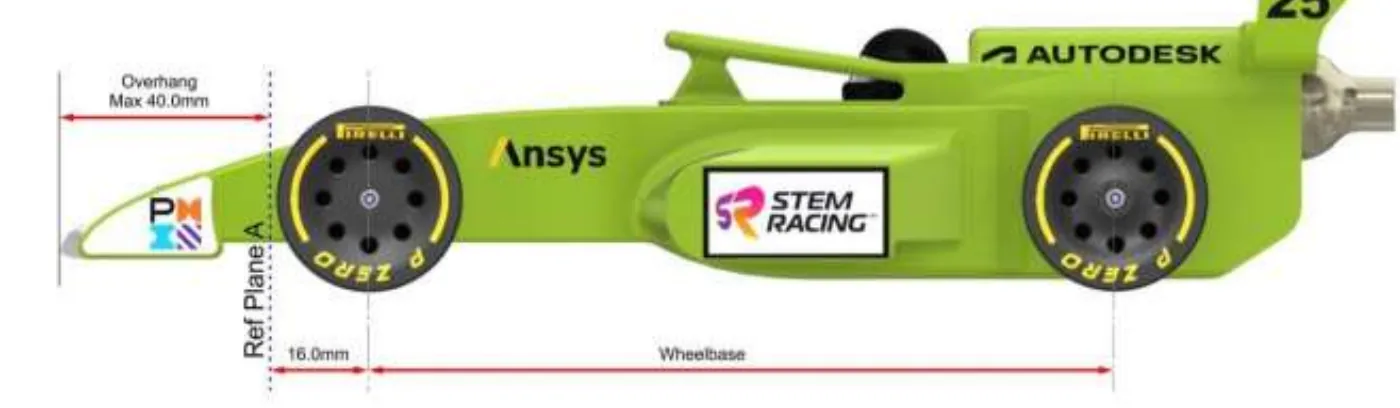
This is measured in front of and parallel to reference plane A to the extreme front of the fully assembled car. From the Reference plane A the nose cone overhang is 40mm maximum.
Absolute Max: 40.0mm
T8.3 Front wing(s) description and placement
[General | Penalty – 5pts]
The design of the car should resemble an actual F1® car through the inclusion of a wing(s) on the nose of the car. Each wing section must have a leading edge and a trailing edge across its full span. Refer to the definition in ARTICLE T1.5.
T8.4 Front wing(s) construction and rigidity
[General | Penalty – 5pts]
The nose, front wing(s) and any support structures may be manufactured from any separate materials. The wing span dimension must remain unchanged during races (i.e. wings must be rigid, ruled at the judge’s discretion).
T8.5 Nose, front wing(s), front wing end plates and wing support location
Nose and wing support structure location - [General | Penalty – 10pts] The nose and front wing support structure must be in front of reference plane A, no more than 25.0mm above the track surface and no wider than 15mm either side of the center line reference plane.
Absolute Max height: 25.0mm
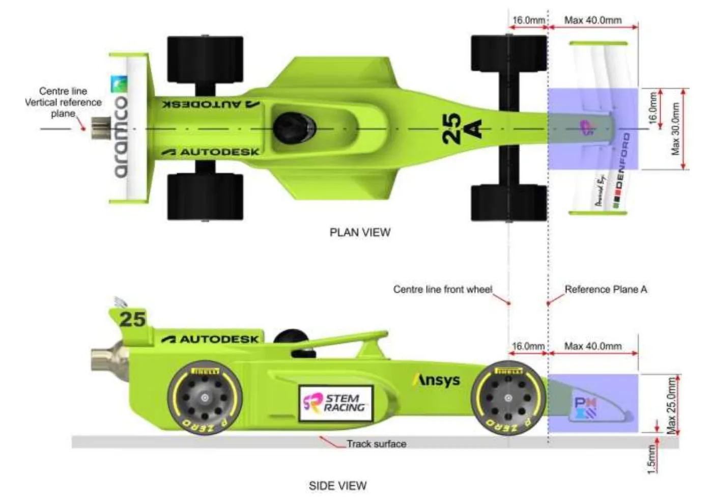
The front wing and front wing end plate location - [General | Penalty – 10pts] The front wing and front wing end plates must be in front of reference plane A. The front wing must be no more than 20.0mm above the track surface when wider than 15mm either side of the center line.
Absolute Max height: 20.0mm
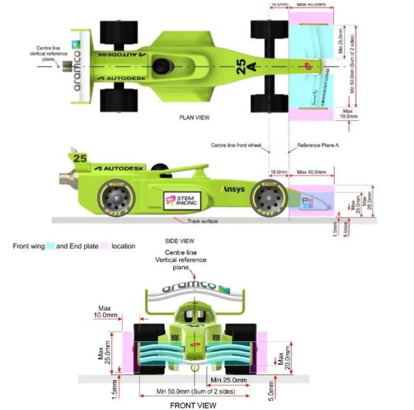
Front wing end plate location - [General | Penalty – 10pts] The front wing endplates must be positioned outside the minimum legal span, with a maximum width of 10.0mm when measured perpendicular to the vertical reference plane, and must not extend more than 25.0mm above the track surface when positioned outside (beyond) the front wheels.
Absolute Max Width: 10.0mm / Absolute Max Height: 25.0mm
The endplates may also play a role in breaking the beam that detects cars crossing the finish line. To maximize accuracy in timing and classification, they should be designed to ensure they reliably trigger the beam as early as possible. Considerations should include their height, width, and position relative to the beam to optimize detection.
Please see Appendix i: Start Box and Finish Gate for beam information.
T8.6 Front wing dimensions
[PERFORMANCE]
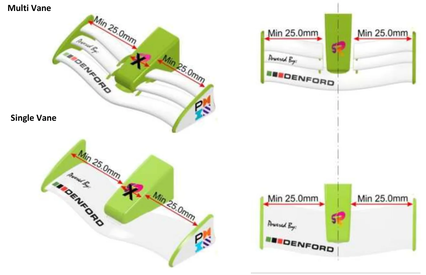
Front wing span - [PERFORMANCE | Penalty – 2pts per millimeter] The front wing span will be measured at right angles to the vertical reference plane along the leading edge, trailing edge, top surface and bottom surface of the wing, whichever is shortest will be considered as the maximum span. Where the front wing span is intersected by another part of the car, the total span is the sum of a maximum of two (2) wing segments, which must be no less than 25.0mm each. (See illustration below)
Absolute Min: 25.0mm x 2 = 50.0mm or 50.0mm x 1 = 50.0mm
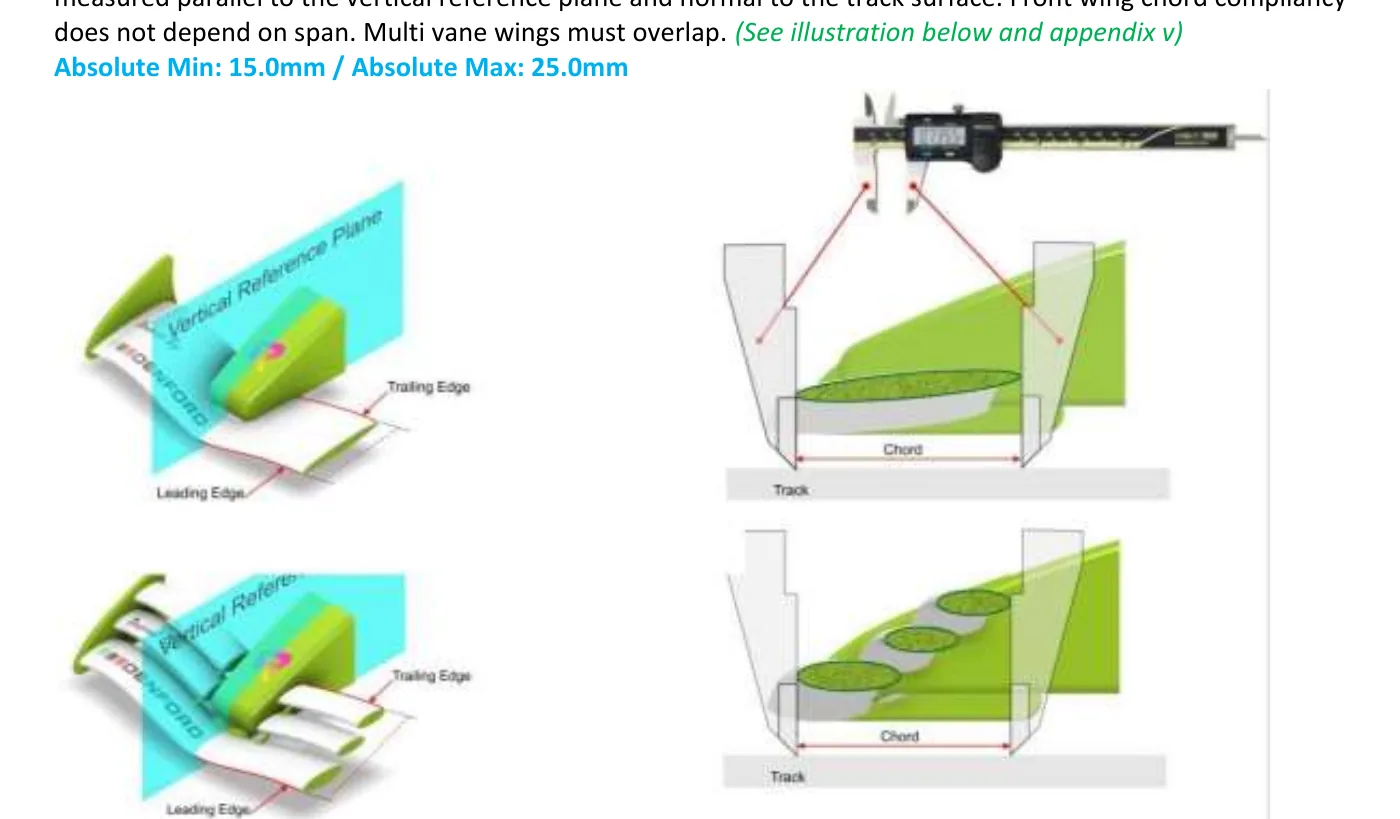
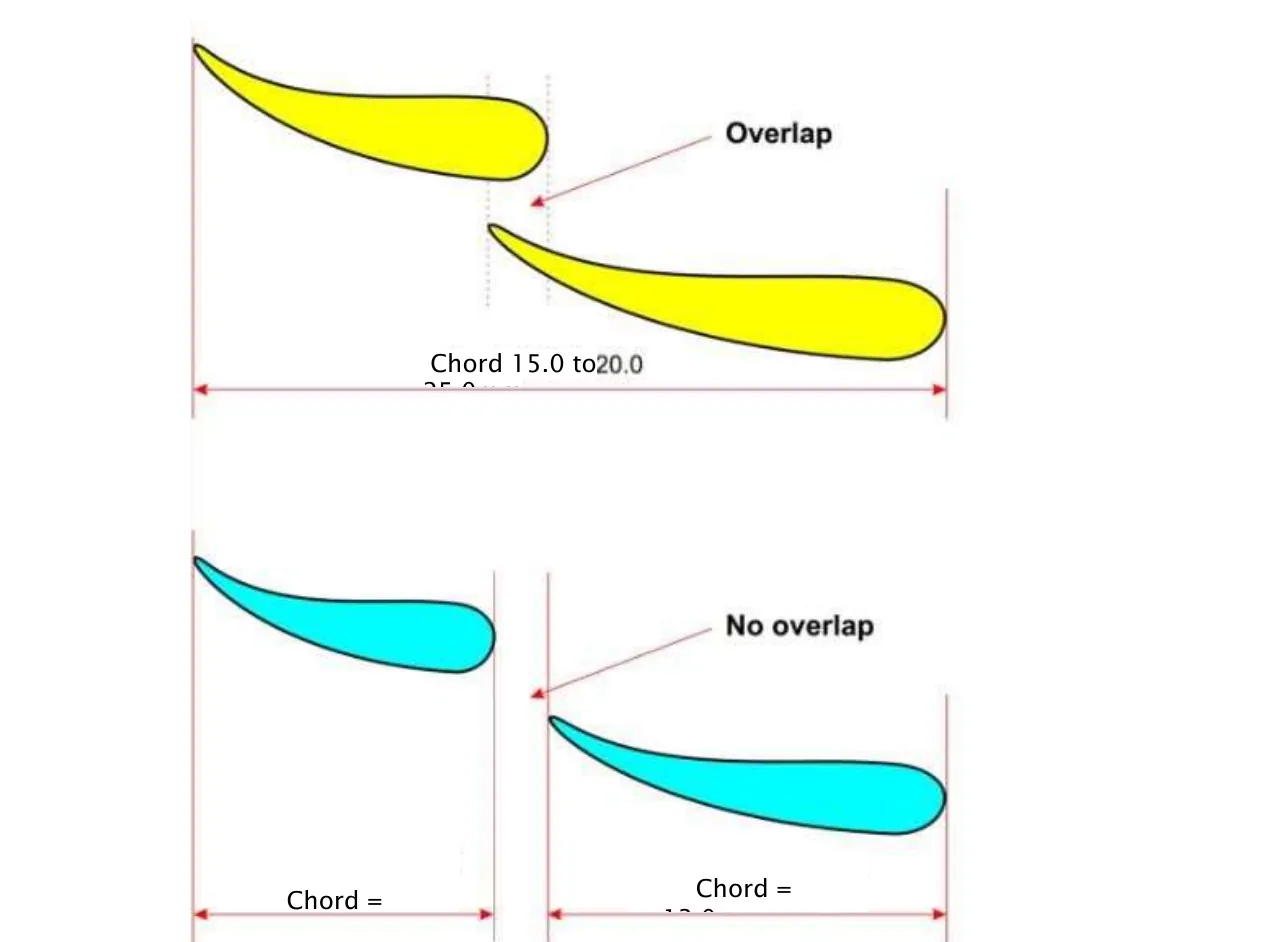
Front wing chord - [PERFORMANCE | Penalty – 1pt per millimeter] The front wing chord minimum to maximum dimensions must exist throughout the existing wing span. The chord is the distance between the leading edge and trailing edge of up to three elements that must overlap, it will be measured parallel to the vertical reference plane and normal to the track surface. Front wing chord compliancy does not depend on span. Multi vane wings must overlap. (See illustration below and appendix v)
Absolute Min: 15.0mm / Absolute Max: 25.0mm
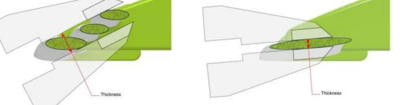
Front wing thickness - [PERFORMANCE | Penalty – 1pt per millimeter] The wing thickness minimum to maximum dimensions must exist throughout the wing’s existing span and at a point along the existing chord. Front wing thickness compliancy does not depend on span and / or chord. (See illustration below)
Absolute Min: 2.0mm / Absolute Max: 6.0mm
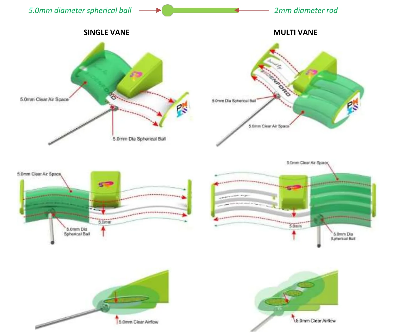
T8.7 Front wing clear airflow
[PERFORMANCE | Penalty – 5pts]
The front wing(s), measured across its / their minimum existing span, must have a minimum of 5.0mm of clear ‘air’ space to any other part of the car or track surface, measured normal from any part of the wings surface.
Absolute Min: 5.0mm
(To allow for fillet rads where a wing joins a support structure this will be checked with a 5.0mm diameter spherical ball on the end of a 2mm diameter rod.)
T8.8 Front wing visibility
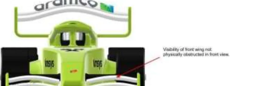
[PERFORMANCE | Penalty – 10pts]
Visibility of the front wing(s) must not be physically obstructed by any other component when viewed in the front view.
Article T9 Rear wing and wing support structures
T9.1 Rear wing and wing support structure identification
[General | Penalty – 5pts]
The surfaces defining the rear wing and wing support structure(s) must be dimensioned and identified clearly by hatching, shading or block color within the engineering drawings submitted for scrutineering. (Clearly labeled construction lines are acceptable to define the boundaries between components such as car body and wheel support structures). Also refer to the definition in ARTICLE T1.15 for guidance on annotating these features in your Engineering Drawings.
T9.2 Rear wing description and placement
[General | Penalty – 5pts]
The design of a STEM Racing™ India car should resemble an actual F1® car through the inclusion of a wing at the rear of the car. To be considered a wing section it must have a leading edge and a trailing edge across its required span. Refer to the definition in ARTICLE T1.5
T9.3 Rear wing construction and rigidity
[General | Penalty – 5pts]
The rear wing and any support structures may be manufactured from any separate materials. The wing span dimension must remain unchanged during races (i.e. wings must be rigid, ruled at the judge’s discretion).
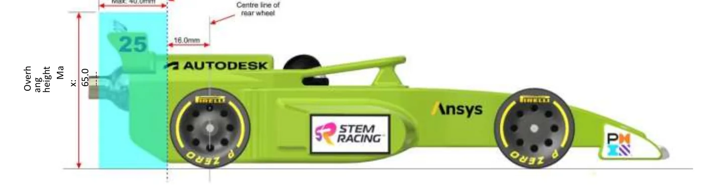
T9.4 Rear wing, wing support structure and rear overhang location
Rear wing and wing support structure location [General | Penalty – 10pts] The whole of the rear wing and any support structure must be to the rear of reference plane B.
Rear overhang length [General | Penalty – 5 pts] This is measured to the rear of and parallel to reference plane B to the extreme rear of the fully assembled car. From the Reference plane B the rear wing and wing support structure overhang is a maximum of 40.0mm.
Absolute Max: 40.0mm
Rear overhang height [General | Penalty – 5 pts] This is measured to the rear of reference plane B to the highest point of the fully assembled car from the track surface.
Absolute Max: 65.0mm
T9.5 Rear wing dimensions
[PERFORMANCE]
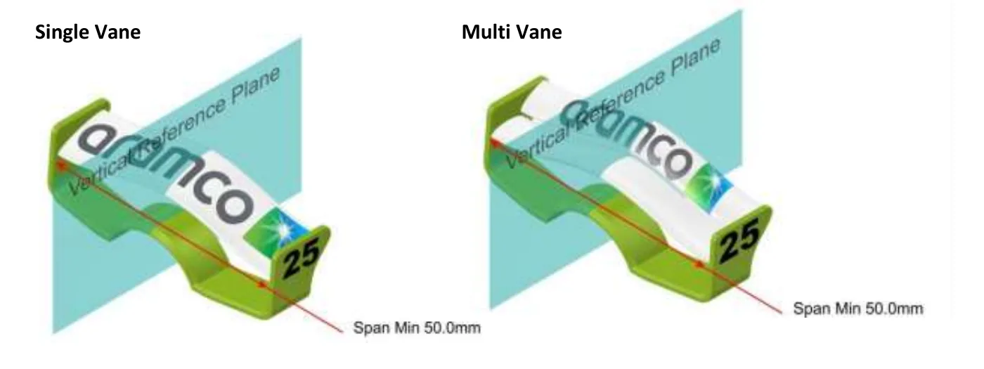
Rear wing span - [PERFORMANCE | Penalty - 2pts per millimeter] The rear wing span will be measured at right angles to the vertical reference plane along the leading edge, trailing edge, top surface or bottom surface of the wing, whichever is shortest will be considered as the maximum span. The rear wing must exist as a single, unbroken minimum span of 50.0mm. (See illustration below)
Absolute Min: 50.0mm
Rear wing chord - [PERFORMANCE | Penalty - 1pt per millimeter] The rear wing chord minimum to maximum dimensions must exist throughout its existing wing span. The chord is the distance between the leading edge and trailing edge of up to two elements that must overlap, it will be measured parallel to the vertical reference plane and normal to the track surface. Rear wing chord compliancy does not depend on span. Multi vane wings must overlap. (See illustration below and appendix v)
Absolute Min: 15.0mm / Absolute Max: 25.0mm
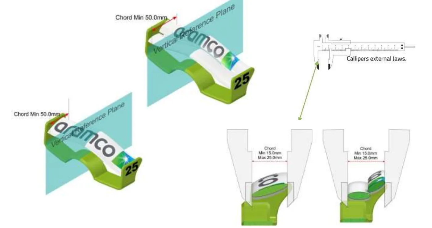
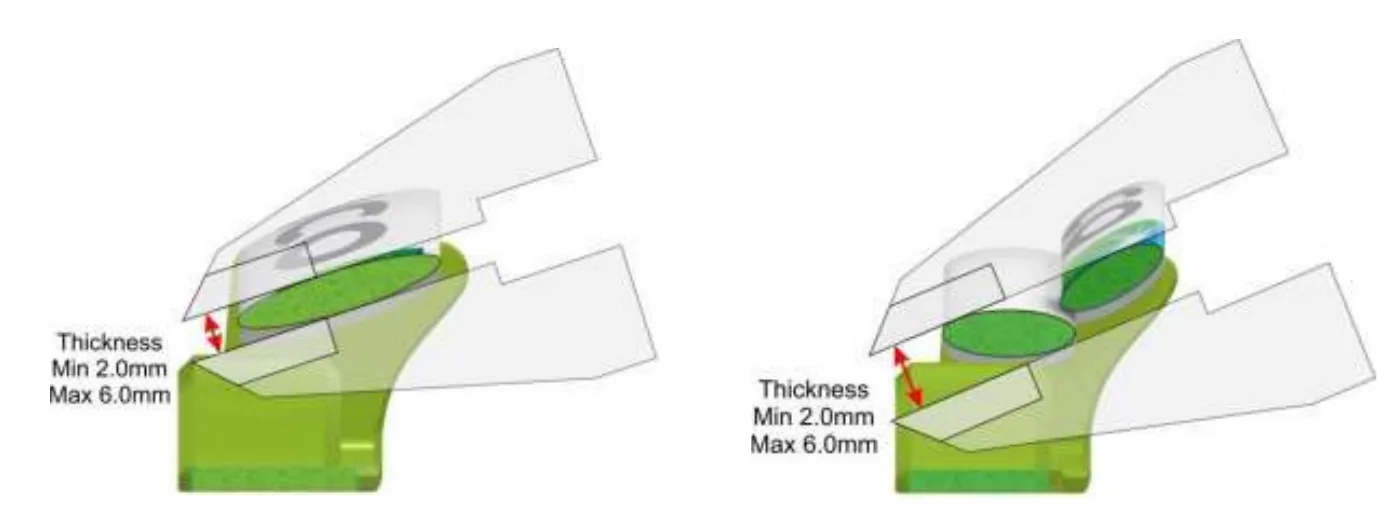
Rear wing thickness - [PERFORMANCE | Penalty - 1pt per millimeter] The wing thickness minimum to maximum dimensions must exist throughout the wing’s existing span and at a point along the existing chord. Rear wing thickness compliancy does not depend on span and / or chord. (See illustration below)
Absolute Min: 2.0mm / Absolute Max: 6.0mm
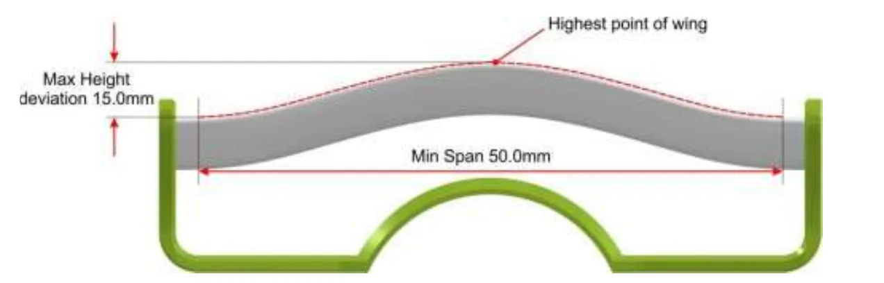
Rear wing height deviation - [GENERAL | Penalty - 1pt per millimeter] The maximum change in height deviation from the highest point of the wing is 15mm. Measured along the minimum span on the top surface.
Absolute maximum height deviation: 15.0mm
T9.6 Rear wing clear airflow
[PERFORMANCE | Penalty – 5pts]
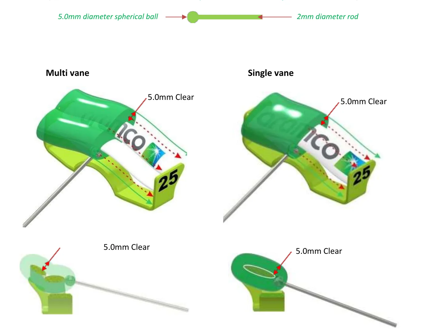
The rear wing, measured across its existing span, must have a minimum of 5.0mm of clear ‘air’ space to any other part of the car or track surface, measured normal from any part of the wings surface.
Absolute Min: 5.0mm
(This will be checked with a 5.0mm diameter spherical ball on the end of a 2mm diameter rod.)
T9.7 Rear wing visibility
[PERFORMANCE | Penalty – 10pts]
Visibility of the rear wing must not be physically obstructed by any other component when viewed in the front view
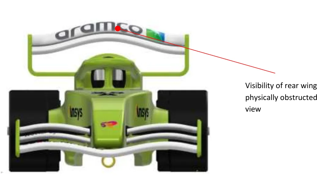
Illustrations for T8 and T9 below:
(See Appendix iii for more detail, examples and penalties relating to wing span, chord and thickness)
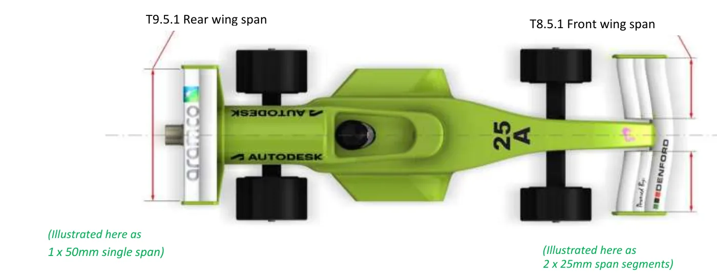
Article T10 Additional components
T10.1 Description and placement
[GENERAL]
Only the power unit cartridge, as positioned by race officials, is permitted to make contact with the launch pods and/or cars prior to and/or during racing. Please refer also to the STEM Racing™ India National Finals 2025/26 Competition Regulations.
Appendix i Start box and finish gate
The start boxes are designed to sit centrally within each lane of the track.
The distance from the emitter center line to the race track surface on both lanes is ~7mm.
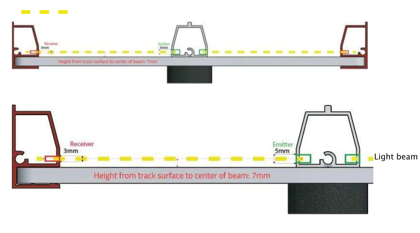
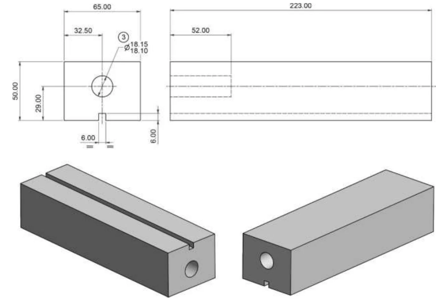
Appendix ii Official STEM Racing™ Model Block dimensions
Below: orthographic projection of STEM RACING™ Model Block. All dimensions shown in millimeters
This component is available to download as a universal 3D part from the below link:
https://drive.google.com/file/d/1Pkl5rM2LZHw7w6vUz8_3LgWxHWf94N5x/view?usp=drive_link
Appendix iii Front wing compliance examples
The following table shows how penalty points are awarded for front wing span, chord or thickness dimensions that do not meet the specifications set out in T8.5.1, T8.5.2 and T8.5.3.
This is not an exhaustive list of all possible wing configurations.
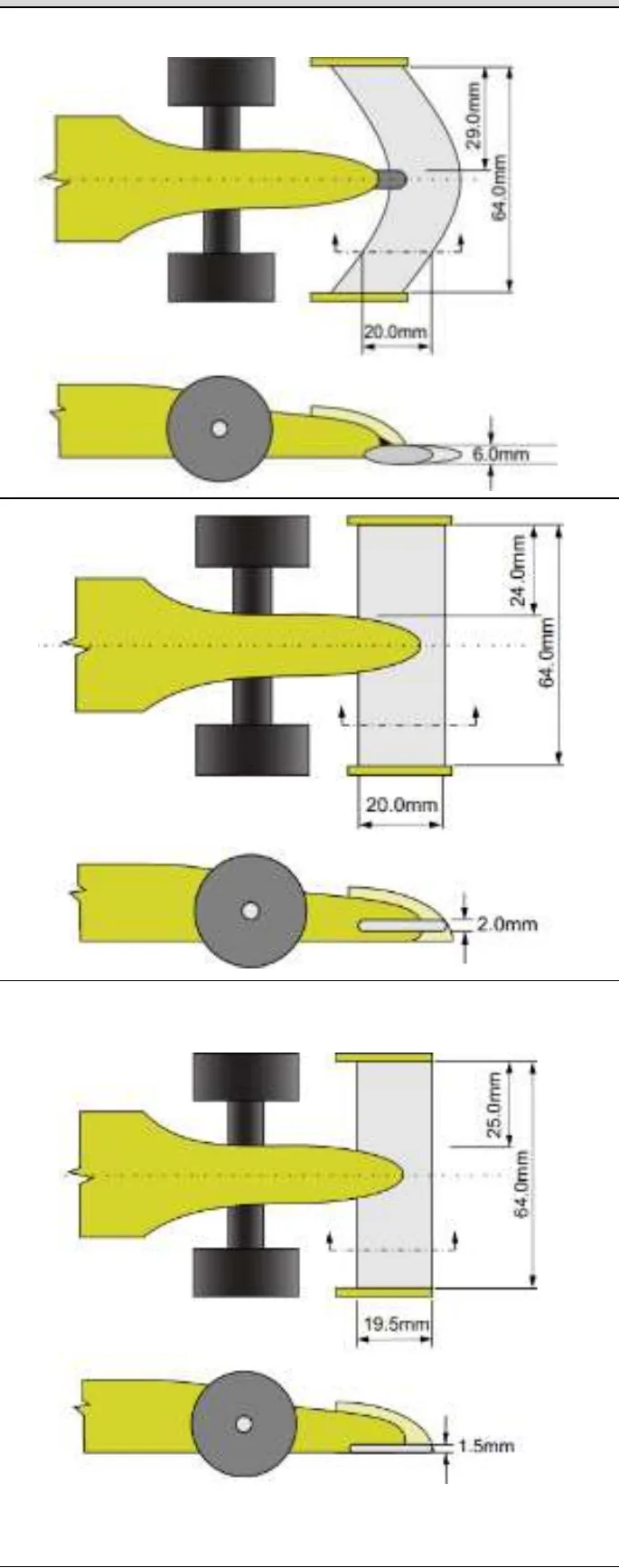
| Example | T8.5.1 Span (-2pts per mm) | T8.5.2 Chord (-1pts per mm) | T8.5.3 Thickness (-1pts per mm) | Remarks |
|---|---|---|---|---|
| Example 1 | PASS | PASS | PASS | Wing span is split by single mounted central wing support. Wing span segments are minimum length, therefore PASS Wing chord is minimum throughout the existing span, therefore PASS. Wing thickness is minimum throughout the wing’s existing span and at a point along the existing chord, therefore PASS. |
| Example 2 | FAIL | PASS | PASS | Wing span is split by nose. Wing span segments are less than minimum length at trailing edge (rear of wing), therefore FAIL Wing chord is minimum throughout the existing span, therefore PASS. Wing thickness is minimum throughout the wing’s existing span and at a point along the existing chord, therefore PASS. |
| Example 3 | PASS | PASS | FAIL | Wing span is split by nose. Wing span segments are minimum length, therefore PASS Wing chord is minimum throughout the existing span, therefore PASS. Wing thickness is less than minimum, therefore FAIL. |
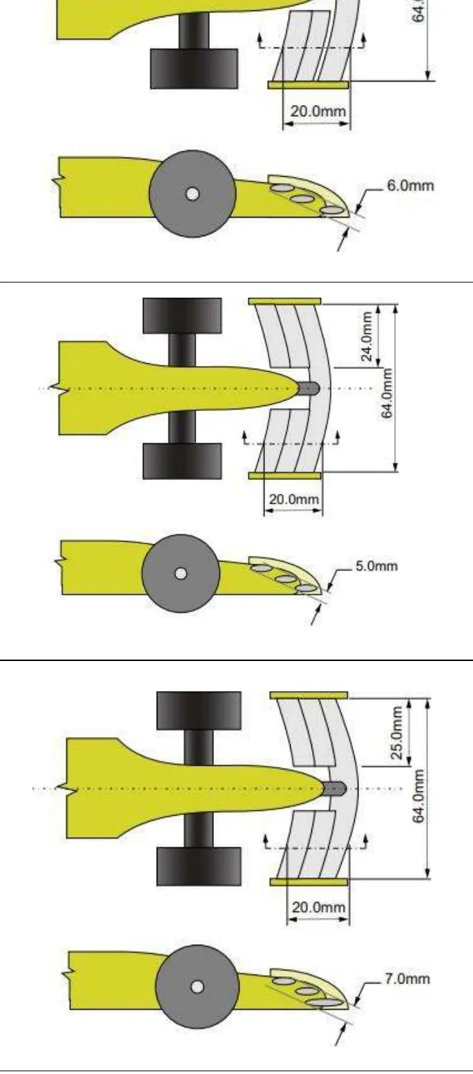
| Example | T8.5.1 Span (-2pts per mm) | T8.5.2 Chord (-1pts per mm) | T8.5.3 Thickness (-1pts per mm) | Remarks |
|---|---|---|---|---|
| Example 1 | PASS | FAIL | PASS | Wing span is split by single mounted central wing support. Wing span segments are minimum length (25mm+25mm), therefore PASS Wing chord is minimum throughout the existing span, but Multi vane wings do not overlap FAIL. Wing thickness is minimum throughout the wing’s existing span and at a point along the existing chord, therefore PASS. |
| Example 2 | FAIL | PASS | PASS | Wing span is split by single mounted central wing support. Wing span segments are less than minimum length at trailing edge (rear of wing), therefore FAIL Wing chord is minimum throughout the existing span, therefore PASS. Wing thickness is minimum throughout the wing’s existing span and at a point along the existing chord, therefore PASS. |
| Example 3 | PASS | PASS | FAIL | Wing span is split by single mounted central wing support. Wing span segments are minimum length (25mm+25mm), therefore PASS Wing chord is minimum throughout the existing span, therefore PASS. Wing thickness is over the maximum limit, therefore FAIL. |
Appendix iv Rear wing compliance examples
The following table shows how penalty points are awarded for rear wing span, chord or thickness dimensions that do not meet the specifications set out in T9.5.1, T9.5.2, T9.5.3, T9.5.4:
This is not an exhaustive list of all possible wing configurations.
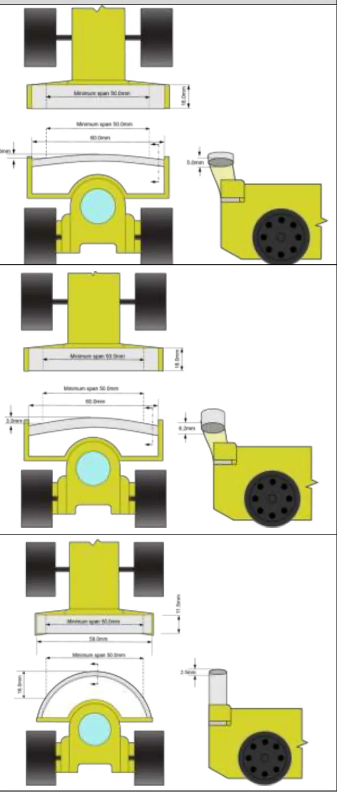
| Example | T9.5.1 Span (-2pts per mm) | T9.5.2 Chord (-1pt per mm) | T9.5.3 Thickness (-1pt per mm) | T9.5.4 Deviation (-1pt per mm) | Remarks |
|---|---|---|---|---|---|
| Example 1 | PASS | PASS | PASS | PASS | Wing span is minimum length, therefore PASS. Wing chord is minimum throughout the existing span, therefore PASS. Wing thickness is minimum throughout the wing’s existing span and at a point along the existing chord, therefore PASS. Rear wing deviation is below maximum, therefore PASS. |
| Example 2 | PASS | PASS | FAIL | PASS | Wing span is minimum length, therefore PASS. Wing chord is minimum throughout the existing span, therefore PASS. Wing thickness is more than maximum, therefore FAIL. Rear wing deviation is below maximum, therefore PASS. |
| Example 3 | PASS | FAIL | PASS | FAIL | Wing span is minimum length, therefore PASS. Wing chord is less than minimum length, therefore FAIL. Wing thickness is minimum throughout the wing’s existing span and at a point along the existing chord, therefore PASS. Wing deviation exceeds maximum height, therefore FAIL. |
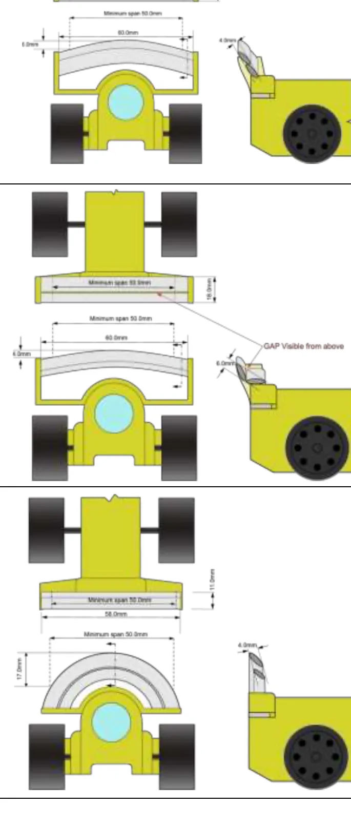
| Example | T9.5.1 Span (-2pts per mm) | T9.5.2 Chord (-1pt per mm) | T9.5.3 Thickness (-1pt per mm) | T9.5.4 Deviation (-1pt per mm) | Remarks |
|---|---|---|---|---|---|
| Example 1 | PASS | PASS | PASS | PASS | Wing span is minimum length, therefore PASS. Wing chord is minimum throughout the existing span, therefore PASS. Wing thickness is minimum throughout the wing’s existing span and at a point along the existing chord, therefore PASS. Wing deviation is minimum throughout the existing span, therefore PASS. |
| Example 2 | PASS | FAIL | PASS | PASS | Wing span is minimum length, therefore PASS. Wing chord is minimum throughout the existing span, but Multi vane wings do not overlap FAIL. Wing thickness is minimum throughout the wing’s existing span and at a point along the existing chord, therefore PASS. Wing deviation is minimum throughout the existing span, therefore PASS. |
| Example 3 | PASS | FAIL | PASS | FAIL | Wing span is minimum length, therefore PASS. Wing chord is less than minimum length, therefore FAIL. Wing thickness is minimum throughout the wing’s existing span and at a point along the existing chord, therefore PASS. Wing deviation exceeds maximum height, therefore FAIL. |
Appendix v Wing overlap
Wing overlap explanation:
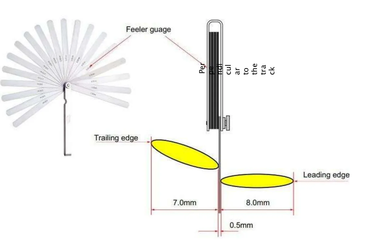
How to check if a gap exists between the elements:
Appendix vi Official Denford Race Power Pack dimensions
This component is available to download as a universal 3D part from the below link:
https://drive.google.com/file/d/1KbsfMYK1KcdzqSJ2Ba7iLrYNOugVN-VH/view?usp=drive_link
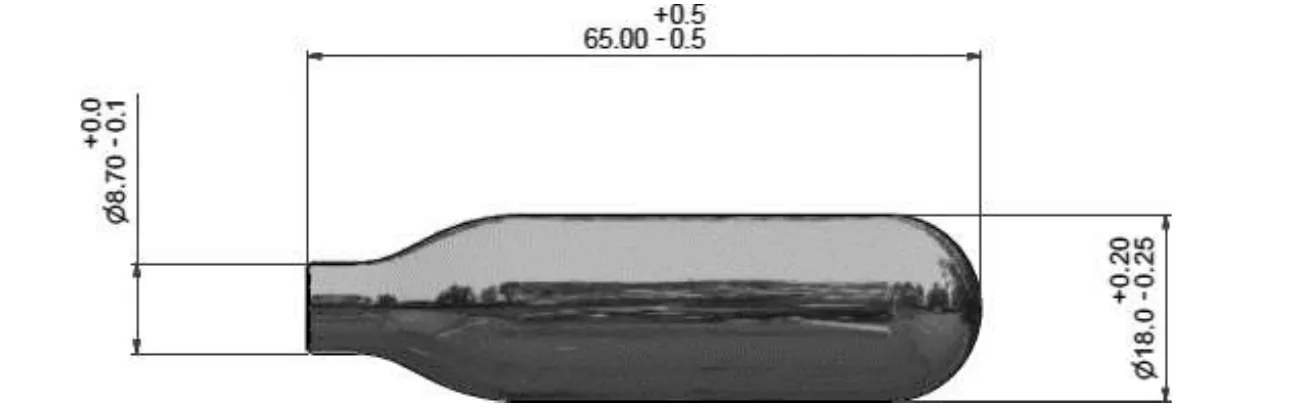
Full weight of RACE Power Pack: between: 28.9g and 29.4g
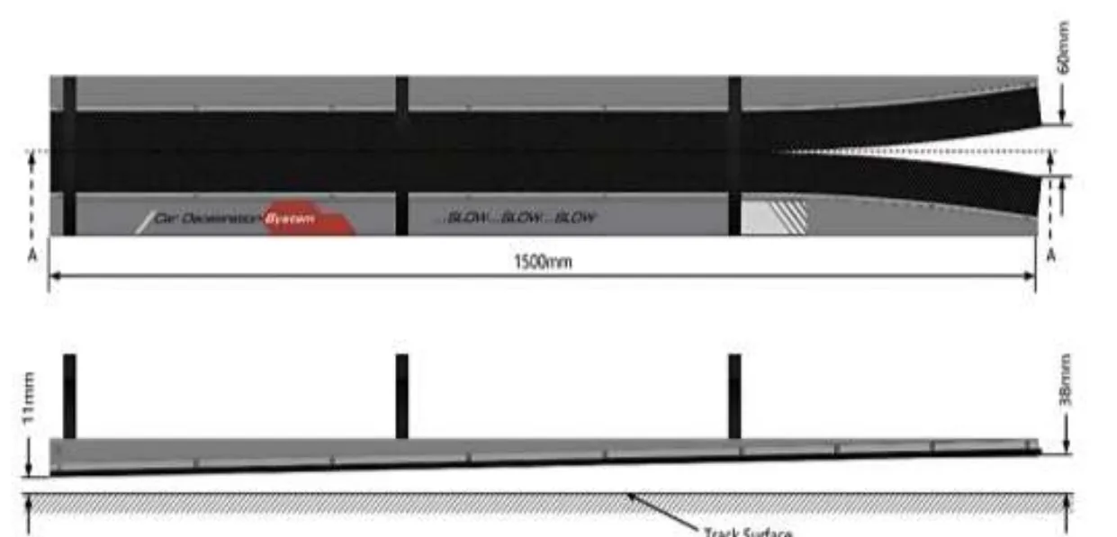
Appendix vii Car deceleration system
The Deceleration System acts to bring cars to rest once crossing the finish line. STEM Racing™ India will provide Deceleration System which is integrated into the final track section after the finish line.
Appendix viii Example of component identification
This is a basic example of component identification. Ensure that the regulation numbers align with the 2025/26 Technical Regulations. For detailed guidance on identifying your components, refer to T1.15.
| Colour | Component |
|---|---|
| Yellow | Front / Rear Wings |
| Coral red | Rear Wing Support |
| Light blue | Front Wing end plate |
| Red | Nose Cone |
| Blue | Wheel Support System |
| Green | Halo |
| Orange | Helmet |
| Light grey | Body |
| Dark grey | Wheels |
| Pink | Tether Guides |
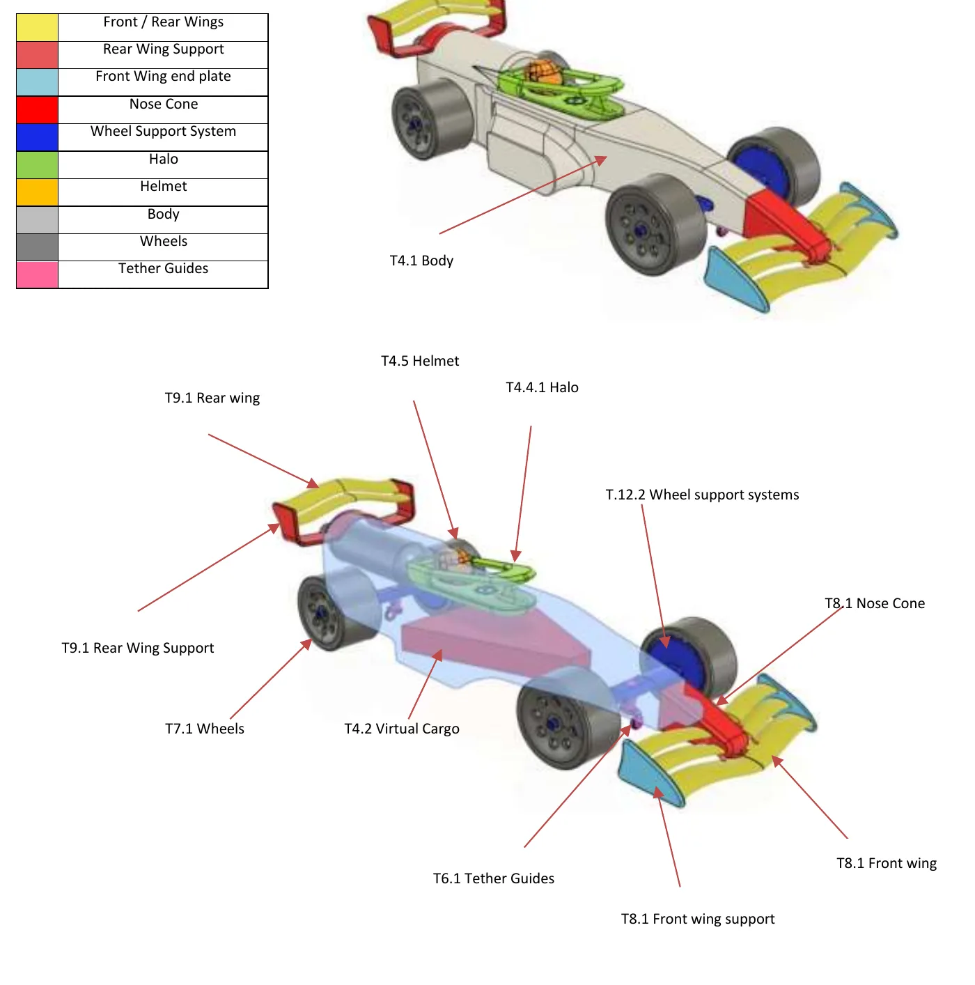
Appendix ix Halo and ballast container drawings
To accommodate the 'Halo', your car will require a pocket cut (which will include a Ballast container directly below the helmet aperture) the dimensions in the drawing below using a 6.35mm (1/4") ball nose tool to a depth of 3.175mm.
The center of the Halo 'Circular notch' for the retardation device is exactly 10.0 mm above the bottom of the pocket. To be effective the center of the Circular Notch must be 34.0mm ±1.0mm above the track surface. To achieve this the bottom of the pocket must be 24.0mm above the track in the assembled car. Use the dimensions on the diagrams below to check you have manufactured your Halo correctly
Legal Ballast
To help achieve the minimum weight, legal ballast may now be added to the legal ballast container under the halo, accessible through the halo/helmet aperture. The Virtual Cargo can coincide with the legal ballast container but not the halo pocket. The helmet should not be glued in place to allow for ballast adjustments before scrutineering.
Demonstration of compliance of Virtual Cargo and Legal Ballast Container
Clarifications
For Official Technical & Competition Regulations Clarifications please email us at competitions@stemplify.com
Work hard, see you at the National Finals!